39
The Sapling Company, Inc.
670 Louis Drive
Warminster, PA 18974
USA
P. (+1) 215.322.6063
F. (+1) 215.322.8498
www.sapling-inc.com
Outputs
Output Relays (Including Sync-Wire)
(
IMPORTANT:
Detach clock from power source before installing new circuitry. DO NOT add new circuitry
while the clock is operating)
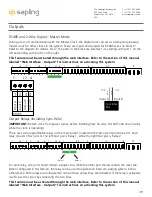
There are two programmable relays on the main board, located on the left side of port block J10. Each
relay consists of two ports. The leftmost pair is Relay 1, while the rightmost pair is Relay 2.
RS485 and 2-Wire Digital - Master Mode
During a loss of communication with the Master Clock, the digital clock can act as a temporary, backup
master clock for other clocks in the system. There are inputs and outputs for RS485 wires on block J7.
Refer to the diagram for details. For J7, the ports in the block are listed as 1-4, starting with port 1 on the
left and ending with port 4 on the right.
This feature must be activated through the web interface. Refer to the section of this manual
labeled “Web Interface - Outputs” for instructions on activating this system
.
Brown
Purple
J7-4
J7-3
Input A
Input B
Converter
Box
3.3V, 100MA
3.3V, 100MA
Timer RX
Temp RX
Common
Timer TX
Temp TX
Not Used
Not Used
Input B+
Output A-
Output B+
Rly1 NO .5A 120vac/24vdc
Rly2 NO .5A 120vac/24vdc
User 1 Input
User 2 Input
User 3 Input
User 4 Input
Common
5V, 40MA
9 -12V, 40MA
Dukane Pulse
Dukane Reset
24Vac Sync
120Vac Sync
AC/DC Com
AUX
5V Dry Cont
(-) Neutral
(+) Line
Earth
1
1
1
1
1
J4
J5
J7
J10
J11
J9
RS485
Common
Input A-
5
5
4
8
10
24 VAC/DC
110/220 VAC
1 2 3 4
RS485
Inp
ut
A
O
ut
pu
t A
O
ut
pu
t B
Inp
ut
B
3.3V, 100MA
3.3V, 100MA
Timer RX
Temp RX
Common
Timer TX
Temp TX
Not Used
Not Used
Input B+
Output A-
Output B+
Rly1 NO .5A 120vac/24vdc
Rly2 NO .5A 120vac/24vdc
User 1 Input
User 2 Input
User 3 Input
User 4 Input
Common
5V, 40MA
9 -12V, 40MA
Dukane Pulse
Dukane Reset
24Vac Sync
120Vac Sync
AC/DC Com
AUX
5V Dry Cont
(-) Neutral
(+) Line
Earth
1
1
1
1
1
J4
J5
J7
J10
J11
J9
RS485
Common
Input A-
5
5
4
8
10
24 VAC/DC
110/220 VAC
3.3V, 100MA
3.3V, 100MA
Timer RX
Temp RX
Common
Timer TX
Temp TX
Not Used
Not Used
Input B+
Output A-
Output B+
Rly1 NO .5A 120vac/24vdc
Rly2 NO .5A 120vac/24vdc
User 1 Input
User 2 Input
User 3 Input
User 4 Input
Common
5V, 40MA
9 -12V, 40MA
Dukane Pulse
Dukane Reset
24Vac Sync
120Vac Sync
AC/DC Com
AUX
5V Dry Cont
(-) Neutral
(+) Line
Earth
1
1
1
1
1
J4
J5
J7
J10
J11
J9
RS485
Common
Input A-
5
5
4
8
10
24 VAC/DC
110/220 VAC
Relay 1
Relay 2
For each relay, one port should contain a power line, while the other port should contain the reset line.
When configured in this fashion, the relay can be used to operate an intercom, paging system, bell or,
other device. Both relays are configured to remain Open unless they are activated. If the relay is activated,
it will close the circuit by connecting the two lines.
This feature must be activated through the web interface. Refer to the section of this manual
labeled “Web Interface - Outputs” for instructions on activating this system
.

