14 15
16 17
28
The Sapling Company, Inc.
670 Louis Drive
Warminster, PA 18974
USA
P. (+1) 215.322.6063
F. (+1) 215.322.8498
www.sapling-inc.com
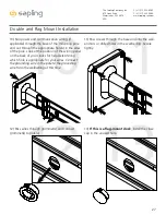
Double and Flag Mount Installation
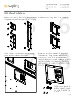
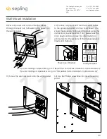
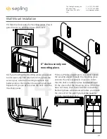
14) Use a Phillips screwdriver to open each wiring
panel. Store the screws in a safe place.
15) Unscrew the seal nuts that cover the gasket
sizes that most closely resemble the diameter
of your power cable. If you are also installing
communication cables, do the same with a second
seal nut and gasket. You may save or discard the
sealing pegs for each gasket that’s being replaced
by a wire.
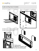
17) Connect all power and communication cables
to the appropriate ports on the circuit board. You
should have already configured the clock using the
instructions provided earlier. If not, please take the
clock down and do so now. For information on
wiring, refer to the sections of this manual labeled
Inputs and Outputs.
3.3V, 100MA
3.3V, 100MA
Timer RX
Temp RX
Common
Timer TX
Temp TX
Not Used
Not Used
Input B+
Output A-
Output B+
Rly1 NO .5A 120vac/24vdc
Rly2 NO .5A 120vac/24vdc
User 1 Input
User 2 Input
User 3 Input
User 4 Input
Common
5V, 40MA
9 -12V, 40MA
Dukane Pulse
Dukane Reset
24Vac Sync
120Vac Sync
AC/DC Com
AUX
5V Dry Cont
(-) Neutral
(+) Line
Earth
1
1
1
1
1
J4
J5
J7
J10
J11
J9
RS485
Common
Input A-
5
5
4
8
10
24 VAC/DC
110/220 VAC
16) Pass all power and communication cables
through the seal nut, followed by the gasket on
the wiring panel.
NOTE: Do not remove the
seal nut or peg if you are
not using the gasket that
it covers.
Power over Ethernet
Locally Powered
If you are installing an elapsed timer, go to “Elapsed Timer Control Panel Installation - Optional Accessory”
If you are installing a temperature sensor, go to “Temperature Sensor Installation - Optional Accessory”

