38
The Sapling Company, Inc.
670 Louis Drive
Warminster, PA 18974
USA
P. (+1) 215.322.6063
F. (+1) 215.322.8498
www.sapling-inc.com
User Input Installation
(
IMPORTANT:
Detach clock from power source before installing new circuitry. DO NOT add new circuitry
while the clock is operating)
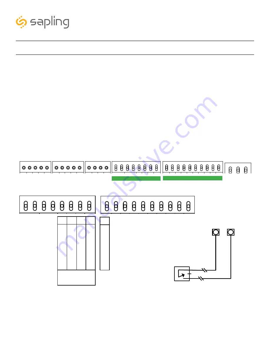
During installation, wires for the inputs should be installed in the appropriate ports on the right side of
block J10, while ground should be run to port 1 on the left side of block J11. Refer to the diagram for
details. The four available inputs are assigned per the diagram below.
Use a dry contact closure between any of the Input ports on J10 and the Common port on J11 activate
one of the numbered user inputs. This input is a
dry contact closure
, which means that
the user should
not be providing external power on either of the lines leading from the relay to the clock.
The
dry contact closure only needs to complete the circuit when activated, and can be a simple switch or
button.
To configure what a given input does to the clock when activated, refer to the section of this manual
labeled “Web Interface - Inputs.”
3.3V, 100MA
3.3V, 100MA
Timer RX
Temp RX
Common
Timer TX
Temp TX
Not Used
Not Used
Input B+
Output A-
Output B+
Rly1 NO .5A 120vac/24vdc
Rly2 NO .5A 120vac/24vdc
User 1 Input
User 2 Input
User 3 Input
User 4 Input
Common
5V, 40MA
9 -12V, 40MA
Dukane Pulse
Dukane Reset
24Vac Sync
120Vac Sync
AC/DC Com
AUX
5V Dry Cont
(-) Neutral
(+) Line
Earth
1
1
1
1
1
J4
J5
J7
J10
J11
J9
RS485
Common
Input A-
5
5
4
8
10
24 VAC/DC
110/220 VAC
5 6 7 8
User Inputs
Inp
ut
1
Inp
ut
4
Inp
ut
3
Inp
ut
2
3.3V, 100MA
3.3V, 100MA
Timer RX
Temp RX
Common
Timer TX
Temp TX
Not Used
Not Used
Input B+
Output A-
Output B+
Rly1 NO .5A 120vac/24vdc
Rly2 NO .5A 120vac/24vdc
User 1 Input
User 2 Input
User 3 Input
User 4 Input
Common
5V, 40MA
9 -12V, 40MA
Dukane Pulse
Dukane Reset
24Vac Sync
120Vac Sync
AC/DC Com
AUX
5V Dry Cont
(-) Neutral
(+) Line
Earth
1
1
1
1
1
J4
J5
J7
J10
J11
J9
RS485
Common
Input A-
5
5
4
8
10
24 VAC/DC
110/220 VAC
The action performed once an input has been
triggered must be configured on the web interface.
Refer to the section of this manual labeled “Web
Interface - Inputs” for more information.
1
C
om
m
on
3.3V, 100MA
3.3V, 100MA
Timer RX
Temp RX
Common
Timer TX
Temp TX
Not Used
Not Used
Input B+
Output A-
Output B+
Rly1 NO .5A 120vac/24vdc
Rly2 NO .5A 120vac/24vdc
User 1 Input
User 2 Input
User 3 Input
User 4 Input
Common
5V, 40MA
9 -12V, 40MA
Dukane Pulse
Dukane Reset
24Vac Sync
120Vac Sync
AC/DC Com
AUX
5V Dry Cont
(-) Neutral
(+) Line
Earth
1
1
1
1
1
J4
J5
J7
J10
J11
J9
RS485
Common
Input A-
5
5
4
8
10
24 VAC/DC
110/220 VAC
J10-5 J11-1
EXAMPLE
(Triggers Input 1)
User
Switch


