


5.2.2
Establishing communication . . . . . . . . . . . . . . . . . . . . . . 49
6
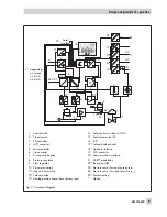
Operator controls and readings
. . . . . . . . . . . . . . . . . . . . 52
6.1
Serial interface . . . . . . . . . . . . . . . . . . . . . . . . . . . . 54
6.2
HART
®
communication . . . . . . . . . . . . . . . . . . . . . . . . 54
6.3
Dynamic HART
®
variables . . . . . . . . . . . . . . . . . . . . . . . 54
7
Start-up – Settings
. . . . . . . . . . . . . . . . . . . . . . . . . . . 56
7.1
Defining the valve closed position . . . . . . . . . . . . . . . . . . . 56
7.2
Setting the volume restriction Q . . . . . . . . . . . . . . . . . . . . 57
7.3
Adapting the display. . . . . . . . . . . . . . . . . . . . . . . . . . 57
7.4
Limiting the signal pressure. . . . . . . . . . . . . . . . . . . . . . . 57
7.5
Checking the operating range of the positioner . . . . . . . . . . . . . 58
7.6
Initialization . . . . . . . . . . . . . . . . . . . . . . . . . . . . . . 59
7.6.1
MAX – Initialization based on maximum range . . . . . . . . . . . . . 60
7.6.2
NOM – Initialization based on nominal range . . . . . . . . . . . . . 61
7.6.3
MAN – Initialization based on a manually selected OPEN position . . . 62
7.6.4
MAN2 – Initialization based on manually selected end positions. . . . . 64
7.6.5
SUB – Substitute calibration . . . . . . . . . . . . . . . . . . . . . . 65
7.6.6
Tuning the KP input filter . . . . . . . . . . . . . . . . . . . . . . . . 68
7.7
Zero calibration . . . . . . . . . . . . . . . . . . . . . . . . . . . . 68
7.8
Settings for on/off valves . . . . . . . . . . . . . . . . . . . . . . . 69
7.9
Reset to default values . . . . . . . . . . . . . . . . . . . . . . . . . 71
8
Operation
. . . . . . . . . . . . . . . . . . . . . . . . . . . . . . . 74
8.1
Enabling and selecting parameters . . . . . . . . . . . . . . . . . . 74
8.2
Operating modes . . . . . . . . . . . . . . . . . . . . . . . . . . . 75
8.2.1
Automatic and manual modes . . . . . . . . . . . . . . . . . . . . . 75
8.2.2
Fail-safe position (SAFE) . . . . . . . . . . . . . . . . . . . . . . . . 76
8.3
Malfunction/Failure . . . . . . . . . . . . . . . . . . . . . . . . . . 76
8.3.1
Confirming error messages . . . . . . . . . . . . . . . . . . . . . . 77
9
Adjusting the limit switch
. . . . . . . . . . . . . . . . . . . . . . . 78
9.1
Retrofitting an inductive limit switch. . . . . . . . . . . . . . . . . . . 80
10
Maintenance
. . . . . . . . . . . . . . . . . . . . . . . . . . . . . 81
11
Servicing explosion-protected devices
. . . . . . . . . . . . . . . . . 81
12
Firmware update (serial interface) . . . . . . . . . . . . . . . . . . . 81
13
Maintenance, calibration and work on equipment
. . . . . . . . . . . 82
14
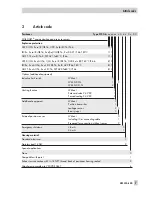
Code list
. . . . . . . . . . . . . . . . . . . . . . . . . . . . . . . 83
4
EB 8384-6 EN
Contents
Summary of Contents for 3730-6
Page 19: ...EB 8384 6 EN 19...
Page 51: ...EB 8384 6 EN 51...
Page 113: ...EB 8384 6 EN 113...
Page 114: ...114 EB 8384 6 EN...
Page 115: ...EB 8384 6 EN 115...
Page 116: ...116 EB 8384 6 EN...
Page 117: ...EB 8384 6 EN 117...
Page 118: ...118 EB 8384 6 EN...
Page 119: ...EB 8384 6 EN 119...
Page 120: ...120 EB 8384 6 EN...
Page 123: ...EB 8384 6 EN 123 diagnostic functions 11 Z Zero calibration 68 Index...


