6
Operator controls and
readings
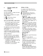
Rotary pushbutton
The rotary pushbutton is located underneath
the front protective cover.
The positioner is operated on site using the
rotary pushbutton:
Turn
to select codes and values.
Press
to confirm setting.
Slide switch AIR TO OPEN or AIR TO CLOSE
4
AIR TO OPEN applies when the increas-
ing signal pressure opens the valve
4
AIR TO CLOSE applies when the increas-
ing signal pressure closes the valve
The signal pressure is the air pressure at the
output of the positioner which is transferred
to the actuator.
For positioners with an attached reversing
amplifier for double-acting rotary actuators
(section 4.5): switch position AIR TO OPEN.
Volume restriction Q
The volume restriction is used to adapt the
air delivery to the actuator size. Two fixed
settings are possible depending on how the
air is routed at the actuator:
4
For actuators smaller than 240 cm² with
a loading pressure connection at the side
(Type 3271-5)
®
MIN SIDE.
4
For actuators 240 cm² and larger, select
MAX SIDE for a side connection.
Readings on display
Icons appear on the display that are as-
signed to parameters, codes and functions.
Operating mode:
– Manual mode (see section 8.2.1)
– Automatic mode (see section 8.2.1)
S
– SAFE (see section 8.2.2)
4
Bar elements:
In
manual and
automatic modes,
the bars indicate the system deviation
that depends on the sign (+/–) and the
value. One bar element appears per 1 %
system deviation.
If the device has not yet been initialized
(
blinks on the display), the lever posi-
tion in degrees in relation to the longitu-
dinal axis is indicated. One bar element
corresponds to approximately a 5° angle
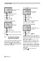
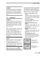
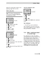
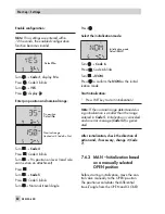
of rotation.
If the fifth bar element blinks (reading
> 30°), the permissible angle of rotation
has been exceeded. Lever and pin posi-
tion must be checked.
4
Status messages
:
Failure
: Maintenance required/Maintenance
demanded
blinks: Out of specification
These icons indicate that an error has oc-
curred.
A classified status can be assigned to
each error. Classifications include 'No
message', 'Maintenance required',
'Maintenance demanded' and 'Failure'
(see section 14).
4
Configuration enabled
Indicates that codes marked with an as-
terisk (*) in the code list (section 14) are
enabled for configuration (section 8.1).
52
EB 8384-6 EN
Operator controls and readings
Summary of Contents for 3730-6
Page 19: ...EB 8384 6 EN 19...
Page 51: ...EB 8384 6 EN 51...
Page 113: ...EB 8384 6 EN 113...
Page 114: ...114 EB 8384 6 EN...
Page 115: ...EB 8384 6 EN 115...
Page 116: ...116 EB 8384 6 EN...
Page 117: ...EB 8384 6 EN 117...
Page 118: ...118 EB 8384 6 EN...
Page 119: ...EB 8384 6 EN 119...
Page 120: ...120 EB 8384 6 EN...
Page 123: ...EB 8384 6 EN 123 diagnostic functions 11 Z Zero calibration 68 Index...


