address/polling address has to be within a
range of 1 to 15.
Note:
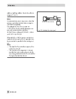
Communication errors may occur when the
process controller/control station output is
not HART-compatible.
For adaptation, the Z box (order no.
1170-2374) can be installed between out-
put and communication interface.
At the Z box a voltage of 330 mV is relea-
sed (16.5
W
at 20 mA).
Alternatively, a 250-
W
resistor can be con-
nected in series and a 22-
m
F capacitor can
be connected in parallel to the analog out-
put.
Note:
–
The load for the controller output will in-
crease as a result.
–
The insertion of a capacitor is not per-
missible for intrinsically safe circuits (Ex
ia), energy-limited circuits (Ex nL) and for
the type of protection Ex nA.
50
EB 8384-6 EN
Connections
22
m
F
250
W
Fig. 20 · Adapting the output signal
Controller/control station
Summary of Contents for 3730-6
Page 19: ...EB 8384 6 EN 19...
Page 51: ...EB 8384 6 EN 51...
Page 113: ...EB 8384 6 EN 113...
Page 114: ...114 EB 8384 6 EN...
Page 115: ...EB 8384 6 EN 115...
Page 116: ...116 EB 8384 6 EN...
Page 117: ...EB 8384 6 EN 117...
Page 118: ...118 EB 8384 6 EN...
Page 119: ...EB 8384 6 EN 119...
Page 120: ...120 EB 8384 6 EN...
Page 123: ...EB 8384 6 EN 123 diagnostic functions 11 Z Zero calibration 68 Index...


