Index
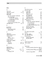
A
Accessories . . . . . . . . . . . . . . 42
Application, type of . . . . . . . . 12, 69
Article code . . . . . . . . . . . . . . . 7
Attachment
acc. to IEC 60534-6 (NAMUR) . . . 26
direct attachment
to Type 3277 Actuator . . . . . 24
to Type 3277-5 Actuator . . . . 22
reversing amplifier . . . . . . . . . 34
to rotary actuators . . . . . . . . . 30
to Type 3510 Micro-flow Valve . . . 28
Automatic mode . . . . . . . . . . 52, 75
B
Bar element . . . . . . . . . . . . . . 52
Binary input . . . . . . . . . . . . . . 13
electrical connection . . . . . . . . 48
technical data . . . . . . . . . . . 18
C
Cable entry . . . . . . . . . . . . . . 47
Closed position of valve . . . . . . . . 56
Communication
HART . . . . . . . . . . . . . 12, 54
TROVIS-VIEW 4 . . . . . . . . . . 12
Condensed state . . . . . . . . . . . . 77
Configuration enabled . . . . . . . 52, 74
Connection
electrical . . . . . . . . . . . 48 - 50
pneumatic . . . . . . . . . . . 45 - 46
D
Default setting . . . . . . . . . . . . . 72
Diagnostic functions . . . . . . . . . . 11
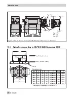
Dimensions. . . . . . . . . . . 109 - 110
Display . . . . . . . . . . . . . . 52 - 53
turning by 180° . . . . . . . . . . 57
E
Electrical connection . . . . . . . . 46, 50
Error messages
confirming . . . . . . . . . . . . . 77
data errors . . . . . . . . . . . . 106
diagnostic errors . . . . . . . . . 107
error appendix . . . . . . . . . . 106
hardware errors . . . . . . . . . 105
initialization errors . . . . . . . . 102
operational errors. . . . . . . . . 104
External position sensor . . . . . . . . 14
attachment
acc. to IEC 60534-6 (NAMUR) . 36
direct attachment . . . . . . . . 34
to rotary actuators . . . . . . . 38
to Type 3510 Micro-flow Valve . 37
electrical connection . . . . . . . . 34
pneumatic connection. . . . . . . . 34
technical data . . . . . . . . . . . 18
F
Fail-safe position (SAFE) . . . . . . . . 76
Failure . . . . . . . . . . . . . . 76 - 77
Firmware update. . . . . . . . . . . . 81
Flow rate calculation . . . . . . . . . . 10
Forced venting . . . . . . . . . . . . . 13
electrical connection . . . . . . . . 48
technical data . . . . . . . . . . . 17
H
HART communication . . . . . . . . . 54
HART protocol . . . . . . . . . . . . . 49
I
Initialization
manually selected end positions (MAN2)
. . . . . . . . . . . . . . . . 59, 64
manually selected OPEN position (MAN)
. . . . . . . . . . . . . . . . 62, 64
maximum range (MAX) . . . . 59 - 60
EB 8384-6 EN
121
Index
Summary of Contents for 3730-6
Page 19: ...EB 8384 6 EN 19...
Page 51: ...EB 8384 6 EN 51...
Page 113: ...EB 8384 6 EN 113...
Page 114: ...114 EB 8384 6 EN...
Page 115: ...EB 8384 6 EN 115...
Page 116: ...116 EB 8384 6 EN...
Page 117: ...EB 8384 6 EN 117...
Page 118: ...118 EB 8384 6 EN...
Page 119: ...EB 8384 6 EN 119...
Page 120: ...120 EB 8384 6 EN...
Page 123: ...EB 8384 6 EN 123 diagnostic functions 11 Z Zero calibration 68 Index...


