


EB 8384-6 EN
9
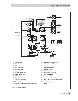
Design and principle of operation
1
Control valve
2
Travel sensor
3
PD controller
4
A/D converter
5
Microcontroller
6
i/p converter
7
Air capacity booster
8
Pressure regulator
9
Flow regulator
10 Volume restriction
11* Inductive limit switch
12* Solenoid valve
13* Analog position transmitter or binary input
14 Software limit switches A1/A2
15 Fault alarm output A3
16 LCD
17* Solenoid valve control
18* Galvanic isolation
19 D/A converter
20 Communication interface
21 HART
®
modulation
22* Binary input BE
23 Pressure sensor for supply pressure p
s
24 Pressure sensor for signal pressure p
out
25* Forced venting
*
Option
%
S
mm
%
mm
PD
FSK
w
x
Q
G
G
Serial
Interface
16
13
22
15
A2
A3
BE
A1
11
2
4
21
20
19
5
3
12
25
6
7
23
8
10
1
14
14
w
x
y
24 V DC
9
17
18
x
1)
>12 V
&
24
Fig. 2 · Functional diagram
x
1)
depending
on version
> 3.8 mA
> 4.4 mA
Summary of Contents for 3730-6
Page 19: ...EB 8384 6 EN 19...
Page 51: ...EB 8384 6 EN 51...
Page 113: ...EB 8384 6 EN 113...
Page 114: ...114 EB 8384 6 EN...
Page 115: ...EB 8384 6 EN 115...
Page 116: ...116 EB 8384 6 EN...
Page 117: ...EB 8384 6 EN 117...
Page 118: ...118 EB 8384 6 EN...
Page 119: ...EB 8384 6 EN 119...
Page 120: ...120 EB 8384 6 EN...
Page 123: ...EB 8384 6 EN 123 diagnostic functions 11 Z Zero calibration 68 Index...


