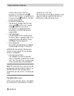
mined safety set point when the
positioner is in automatic mode
(AUTO). This function is not performed in
the manual mode
(MAN) or fail-safe
position mode (SAFE).
4
Switch AUTO/MANUAL
The positioner changes from the auto-
matic mode
(AUTO) to the manual
mode
(MAN) or vice versa.
This function is not performed if the
positioner is in the fail-safe position
mode (SAFE).
4
Start data logger
The data logger starts recording when
the binary input is activated (refer to Op-
erating Instructions EB 8389-1 EN on
EXPERTplus Valve Diagnostics).
4
Reset diagnostics
Active tests and monitoring are stopped
and the diagnostic data is reset once.
Additionally, the external solenoid valve
function can be selected if a non-floating
contact is configured:
4
External solenoid valve
The voltage for an external solenoid
valve is connected in parallel to terminals
+81/–82. This allows the switching state
of the solenoid valve to be monitored.
Note:
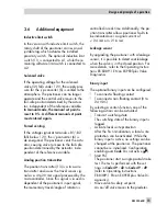
The optional binary input can only be
configured using the operator software e.g.
TROVIS-VIEW 4. The switching state is
transmitted when the switch is closed by de-
fault.
External position sensor
In this version, only the sensor is mounted to
the control valve. The positioner is located
separately from the valve.
The connection of controlled variable (x) and
output variable (y) signals to the valve is es-
tablished by cable and piping for air.
14
EB 8384-6 EN
Design and principle of operation
Summary of Contents for 3730-6
Page 19: ...EB 8384 6 EN 19...
Page 51: ...EB 8384 6 EN 51...
Page 113: ...EB 8384 6 EN 113...
Page 114: ...114 EB 8384 6 EN...
Page 115: ...EB 8384 6 EN 115...
Page 116: ...116 EB 8384 6 EN...
Page 117: ...EB 8384 6 EN 117...
Page 118: ...118 EB 8384 6 EN...
Page 119: ...EB 8384 6 EN 119...
Page 120: ...120 EB 8384 6 EN...
Page 123: ...EB 8384 6 EN 123 diagnostic functions 11 Z Zero calibration 68 Index...


