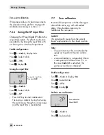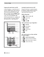
WARNING!
To avoid personal injury or property dam-
age caused by the supply air or electrical
auxiliary power, disconnect the supply air
and electrical auxiliary power before ex-
changing the lever or changing the pin posi-
tion.
7.6
Initialization
WARNING!
During initialization, the control valve moves
through its entire travel/angle of rotation
range. Therefore, do not start the initializa-
tion procedure while a process is running,
but only during start-up when all shut-off
valves are closed.
Before starting initialization, check the maxi-
mum permissible signal pressure of the con-
trol valve. During initialization, the
positioner issues an output signal pressure
up to the maximum supply pressure sup-
plied. If necessary, limit the signal pressure
by connecting an upstream pressure reduc-
ing valve.
NOTICE
After the positioner has been mounted on to
another actuator or its mounting location
has been changed and prior to
re-initializing the positioner, the positioner
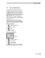
needs to be reset to its basic setting (default
values). Refer to section 7.9.
Note:
When the write protection
is acti-
vated, the initialization cannot be started.
During initialization the positioner adapts it-
self optimally to the friction conditions and
the signal pressure demand of the control
valve. The type and extent of self-adaptation
depends on the set initialization mode:
4
Maximum range (
MAX)
(standard
range)
Initialization mode for simple start-up of
valves with two clearly defined mechani-
cal end positions, e.g. three-way valves
(see section 7.6.1)
4
Nominal range (
NOM)
Initialization mode for all globe valves
(see section 7.6.2)
4
Manually selected OPEN position
(
MAN)
Initialization mode for globe valves with
manual entry of the OPEN position (see
section 7.6.3)
4
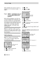
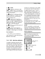
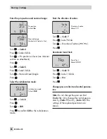
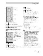
Manually selected end positions
(
MAN2)
Initialization mode for globe valves with
manual entry of both positions (see sec-
tion 7.6.4)
4
Substitute calibration
(
SUB)
This mode allows a positioner to be re-
placed while the plant is running, with
the least amount of disruption to the
plant (see section 7.6.5)
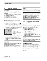
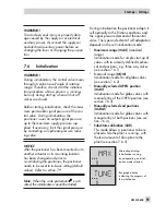
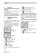
Alternating displays
Initialization running
Icon depending on initial-
ization mode selected
Bar graph display
indicating the progress of
the initialization
EB 8384-6 EN
59
Start-up – Settings
Summary of Contents for 3730-6
Page 19: ...EB 8384 6 EN 19...
Page 51: ...EB 8384 6 EN 51...
Page 113: ...EB 8384 6 EN 113...
Page 114: ...114 EB 8384 6 EN...
Page 115: ...EB 8384 6 EN 115...
Page 116: ...116 EB 8384 6 EN...
Page 117: ...EB 8384 6 EN 117...
Page 118: ...118 EB 8384 6 EN...
Page 119: ...EB 8384 6 EN 119...
Page 120: ...120 EB 8384 6 EN...
Page 123: ...EB 8384 6 EN 123 diagnostic functions 11 Z Zero calibration 68 Index...


