nection, an additional cable gland can be
installed.
Seal cable entries left unused with plugs.
Devices used at ambient temperatures
be-
low –20 °C
must be fitted with metal cable
glands.
Equipment for use in zone 2/zone 22
In equipment operated with type of protec-
tion EEx nA II (non-sparking equipment) ac-
cording to EN 60079-15 (2003), circuits
may be connected, interrupted or switched
while energized only during installation,
maintenance or repair.
Equipment connected to energy-limited cir-
cuits with type of protection Ex nL (en-
ergy-limited equipment) according to EN
60079-15 (2003) may be switched under
normal operating conditions.
The maximum permissible values specified
in the national explosion protection certifi-
cates also apply when interconnecting the
equipment with energy-limited circuits in
type of protection Ex nL IIC/IIB.
Cable entries
The cable entry with M20 x 1.5 cable gland,
6 to 12 mm clamping range.
There is a second M20 x 1.5 threaded bore
in the housing that can be used for addi-
tional connection, when required.
The screw terminals are designed for wire
cross-sections of 0.2 to 2.5 mm². Tighten by
at least 0.5 Nm.
The wires for the reference variable must be
connected to the terminals 11 and 12 lo-
cated in the housing.
Only use
a current source
!
³
3.6 mA: Microprocessor and display active
< 3.7 mA:
LOW
on display
£
3.8 mA: Emergency shutdown
> 3.9 mA: Actuator can be filled with air
> 22 mA:
OVERLOAD
on display
In general, it is not necessary to connect the
positioner to a bonding conductor. Should
this be required, however, this conductor
can be connected inside the device.
Depending on the version, the positioner is
equipped with inductive limit switches
and/or a solenoid valve.
The position transmitter is operated on a
two-wire circuit. The usual supply voltage is
24 V DC. Considering the resistance of the
supply leads, the voltage at the position
transmitter terminals can be between 12 V
and 30 V DC.
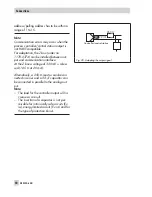
Refer to Fig. 18 or the label on the terminal
strip for terminal assignment.
EB 8384-6 EN
47
Connections
Summary of Contents for 3730-6
Page 19: ...EB 8384 6 EN 19...
Page 51: ...EB 8384 6 EN 51...
Page 113: ...EB 8384 6 EN 113...
Page 114: ...114 EB 8384 6 EN...
Page 115: ...EB 8384 6 EN 115...
Page 116: ...116 EB 8384 6 EN...
Page 117: ...EB 8384 6 EN 117...
Page 118: ...118 EB 8384 6 EN...
Page 119: ...EB 8384 6 EN 119...
Page 120: ...120 EB 8384 6 EN...
Page 123: ...EB 8384 6 EN 123 diagnostic functions 11 Z Zero calibration 68 Index...


