ECL Comfort 100M
User’s Guide and Installation
*087R9728*
*vi7ab402*
2004.05
Page 1: ...ECL Comfort 100M User s Guide and Installation ECL Comfort 100M User s Guide and Installation 087R9728 vi7ab402 2004 05 087R9728 vi7ab402 2004 05...
Page 2: ...trical connections 26 LED indication 29 Check list 30 Communication 32 Power back up 34 De nitions 36 Table of contents Page No User s Guide Before you start 3 Operating the controller 4 Setting the c...
Page 3: ...ble temperatures when you are at home and helps you save energy and thus reduce costs while you are out User s Guide Before you start Save energy save money improve your comfort temperature The ECL Co...
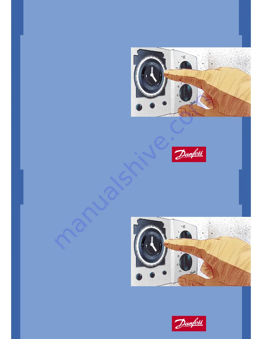
Page 4: ...you set the heating system to reduce temperature at the corresponding period of time Setting the clock Operating the controller 18 12 6 1 8 1 2 6 1 8 1 2 6 1 8 1 2 6 1 8 1 2 6 1 8 1 2 6 12 3 6 9 Cloc...
Page 5: ...ay etc Standby Heating is stopped The system is protected against frost Use this mode during the summer What do the symbols mean Controller mode 18 12 6 1 8 1 2 6 1 8 1 2 6 1 8 1 2 6 1 8 1 2 6 1 8 1 2...
Page 6: ...from 12 to 28 C Temperature setting 18 12 6 1 8 1 2 6 1 8 1 2 6 1 8 1 2 6 1 8 1 2 6 1 8 1 2 6 12 3 6 9 Adjustments With room sensor If the wanted comfort temperature is not reached Make sure that the...
Page 7: ...e outdoor temperature However the temperature will not be reduced if the outdoor temperature is below 8 C Temperature reduction in reduced temperature mode You can choose how many degrees you want the...
Page 8: ...the heat curve Outdoor temperature Radiator circuit Floor heating 25 C 1 2 0 5 15 C 1 6 0 6 10 C 1 8 0 7 The heat curve shows the relation between the outdoor temperature and the ow temperature of th...
Page 9: ...FF 10 C ON 35 C Switch 1 Heating cut out Switch 1 Cut out temperature Your setting OFF No cut out ON 18 C Controller settings on the rear side To make the controller ready for operation you must adjus...
Page 10: ...F ON OFF 2 built in ON ON OFF 3 built in OFF OFF ON 4 ECA 60 61 address A ON OFF ON 5 ECA 60 61 address B Set a maximum ow temperature to protect your heating system from getting overheated The runnin...
Page 11: ...use of energy resources The automatic pump motion program protects the circulation pump against blocking Installation and maintenance Before you start Save energy save money improve your comfort temp...
Page 12: ...sary in heating systems Heating system type 2 Boiler system Heating system type 1 Direct district heating Identifying the system type The ECL Comfort controller is capable of controlling di erent heat...
Page 13: ...r mounting kit No 087B1145 A mounting kit is necessary to mount the box with the controller on a DIN rail You should mount the ECL Comfort controller for easy access near the heating unit You can choo...
Page 14: ...r ESM 11 Do not move the sensor after it has been fastened in order to avoid damage to the sensor element It is important that the sensors are mounted in the correct position in your heating system Ou...
Page 15: ...rted in each screw terminal max cable length 50 m Important Wrong connections cause damaged TRIAC outlets Electrical connections 230 V a c Establish these jumpers Jumper from 1 to 5 Jumper from 5 to 1...
Page 16: ...7 and 16 Outdoor sensor S1 ESMT 18 and 16 Room sensor S2 ESM 10 19 and 16 Flow sensor S3 ESMU ESM 11 ESMC Electrical connections sensors Establish the jumper from 16 to common terminal Cable cross sec...
Page 17: ...s are connected to the correct terminals See page 28 Electrical connections sensor Mount the controller switch on the power You can check the turning direction of the motorized valve either by looking...
Page 18: ...slave has the address 0 only the outdoor temperature signal is transferrred from the master to the slave Communication The ECL Comfort controller can be connected to external units via the ECL Comfor...
Page 19: ...e AAA 1 5 V type Remove the battery holder and replace the battery Remount the holder again Power back up 18 12 6 1 8 1 2 6 1 8 1 2 6 1 8 1 2 6 1 8 1 2 6 1 8 1 2 6 12 3 6 9 Power back up for your ECL...
Page 20: ...uring daytime Function selector A facility which makes it possible to override the mode of the controller Heating circuit The circuit for heating the room building Pt 1000 ohm sensor All sensors used...
Page 21: ...38 38 39 39...