Rockwell Automation Publication 193-UM015D-EN-P - February 2015
499
Parameter List
Appendix
B
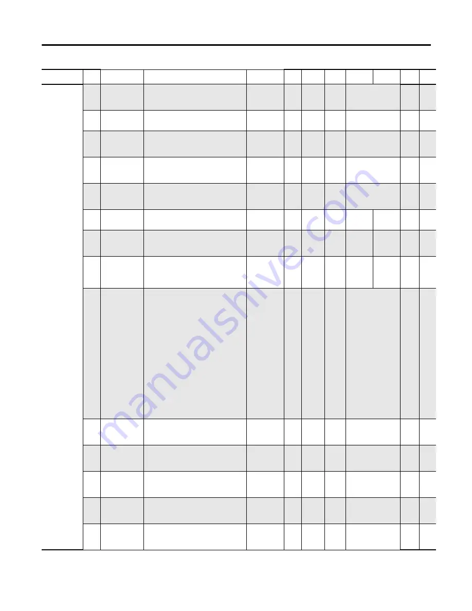
Analog4 Setup
(continued)
540
InAMod4Ch1Format
C.Analog4.Ch01InputFormat_0
C.Analog4.Ch01InputFormat_1
C.Analog4.Ch01InputFormat_2
Assignment for
Analog Module 4
Input Channel 01
Data Format
USINT
1
1
0= EngUnits
1= EngUnitsTimes10
2= RawProportional
3= ScaledForPID
0
541
InAMod4C1TmpUnit
C.Analog4.Ch01InputTempMode
Module 4 Input
Channel 01
Temperature Units
USINT
1
1
0=DegreesC
1=DegreesF
0
542
InAMod4C1FiltFrq
C.Analog4.Ch01InputFilter_0
C.Analog4.Ch01InputFilter_1
C.Analog4.Ch01InputFilter_2
Assignment
Analog Module 4
Input Channel 01
Filter Freq
USINT
1
1
0=17Hz
1=4Hz
2=62Hz
3=470Hz
0
543
InAMod4C1OpCktSt C.Analog4.Ch01InputOpenWire_0
C.Analog4.Ch01InputOpenWire_1
Indicates Analog
Module 4 Input
Channel 01 Open
Circuit State
USINT
1
1
0=Upscale
1=Downscale
2=Zero
0
544
InAnMod4Ch1RTDEn
C.Analog4.Ch01InputTwoWireRTD
Enable Analog
Module 4Input
Channel 01 to
function with RTD
BOOL
1
1
0=3-wire
1=2-wire
0
545
InAMod4C1TripDly
C.Analog4.Ch01InputTripDelay
Analog Module 4
Input Channel 01
Trip Delay
USINT
1
10
0
250
10
Second
s
546
InAMod4C1TripLvl
C.Analog4.Ch01InputTripLimit
Level (in selected
Units) where
Analog Input
generates a trip
UINT
2
1
-32768
32767
0
547
InAMod4C1WarnLvl
C.Analog4.Ch01InputWarnLimit
Level (in selected
Units) where
Analog Input
generates a
warning
UINT
2
1
-32768
32767
0
548
InAnMod4Ch02Type
C.Analog4.Ch02InputRangeType_0
C.Analog4.Ch02InputRangeType_1
C.Analog4.Ch02InputRangeType_2
C.Analog4.Ch02InputRangeType_3
C.Analog4.Ch02InputRangeType_4
Assignment for
Analog Module 4
Input Channel 02
function
USINT
1
1
0= Disabled
1= 4To20mA
2= 0To20mA
3= 0To10Volts
4= 1To5Volts
5= 0To5Volts
6= 100Pt385
7= 200Pt385
8= 500Pt385
9= 1000Pt385
10=100Pt3916
11= 200Pt3916
12= 500Pt3916
13= 1000Pt3916
14= 10Cu426
15= 120Ni618
16= 120Ni672
17= 604NiFe518
18= 150ohm
19= 1000ohm
20 = 3000ohm
21= 6000ohm
0
549
InAMod4Ch2Format
C.Analog4.Ch02InputFormat_0
C.Analog4.Ch02InputFormat_1
C.Analog4.Ch02InputFormat_2
Assignment for
Analog Module 4
Input Channel 02
Data Format
USINT
1
1
0= EngUnits
1= EngUnitsTimes10
2= RawProportional
3= ScaledForPID
0
550
InAMod4C2TmpUnit
C.Analog4.Ch02InputTempMode
Assignment for
Analog Module 4
Input Channel 02
Temperature Units
USINT
1
1
0=DegreesC
1=DegreesF
0
551
InAMod4C2FiltFrq
C.Analog4.Ch02InputFilter_0
C.Analog4.Ch02InputFilter_1
C.Analog4.Ch02InputFilter_2
Indicates Analog
Module 4 Input
Channel 02 Filter
Freq
USINT
1
1
0=17Hz
1=4Hz
2=62Hz
3=470Hz
0
552
InAMod4C2OpCktSt
C.Analog4.Ch02InputOpenWire_0
C.Analog4.Ch02InputOpenWire_1
Indicates Analog
Module 4 Input
Channel 02 Open
Circuit State
USINT
1
1
0= Zero
1= Maximum
2= Minimum
3= HoldLastState
0
553
InAnMod4Ch2RTDEn
C.Analog4.Ch02InputTwoWireRTD
Enable Analog
Module 4 Input
Channel 02 to
function with RTD
BOOL
1
1
0=Disable
1=Enable
0
Group
Param
No.
Parameter Name
Device Profile Tag Name
Description
Type
Data Size
(bytes)
Scale
Factor
Min
Max
Default Units
Summary of Contents for Allen-Bradley E300
Page 1: ...E300 Electronic Overload Relay Bul 193 592 User Manual...
Page 128: ...128 Rockwell Automation Publication 193 UM015D EN P February 2015 Chapter 5 Operating Modes...
Page 304: ...304 Rockwell Automation Publication 193 UM015D EN P February 2015 Chapter 7 Commands Notes...
Page 502: ...502 Rockwell Automation Publication193 UM015D EN P November 2013 Appendix B Parameter List...
Page 545: ......


