Rockwell Automation Publication 193-UM015D-EN-P - February 2015
147
Protective Trip and Warning Functions
Chapter 6
•
Ground Fault Current is equal to or greater than the Ground Fault
Warning Level for a time period greater than the Ground Fault Warning
Delay.
When the ground fault warning conditions are satisfied, the:
•
TRIP/WARN LED status indicator flashes a yellow 3-short blink pattern
•
Bit 2 in Current Warning Status (Parameter 10) sets to 1
•
Bit 1 of Device Status 0 (Parameter 20) sets to 1
•
Any relay outputs configured as a Warning Alarm close
Ground Fault Warning Level
Ground Fault Warning Level (Parameter 246) allows you to define the ground
fault current at which the E300 Electronic Overload Relay indicates a warning
and is adjustable from 0.20…5.00 A.
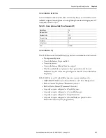
Table 181 - Ground Fault Warning Level (Parameter 246)
Ground Fault Warning Delay
Ground Fault Warning Delay (Parameter 245) allows you to define the time
period (adjustable from 0.0…25.0 s) for which a ground fault condition must be
present before a warning occurs.
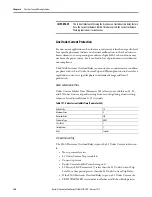
Table 182 - Ground Fault Warning Delay (Parameter 245)
Ground Fault Warning Level (Parameter 246)
Default Value
2.00
Minimum Value
0.20
Maximum Value
5.00
Parameter Type
UINT
Size (Bytes)
2
Scaling Factor
100
Units
Amps
Ground Fault Warning Delay (Parameter 245)
Default Value
0.0
Minimum Value
0.0
Maximum Value
25.00
Parameter Type
USINT
Size (Bytes)
1
Scaling Factor
10
Units
Seconds
Summary of Contents for Allen-Bradley E300
Page 1: ...E300 Electronic Overload Relay Bul 193 592 User Manual...
Page 128: ...128 Rockwell Automation Publication 193 UM015D EN P February 2015 Chapter 5 Operating Modes...
Page 304: ...304 Rockwell Automation Publication 193 UM015D EN P February 2015 Chapter 7 Commands Notes...
Page 502: ...502 Rockwell Automation Publication193 UM015D EN P November 2013 Appendix B Parameter List...
Page 545: ......


