Rockwell Automation Publication 193-UM015D-EN-P - February 2015
271
Protective Trip and Warning Functions
Chapter 6
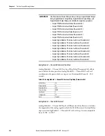
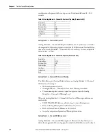
Relay trips on an Analog Module 2 – Channel 00 Over Level warning. It is user-
adjustable from -32768…+32767.
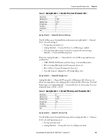
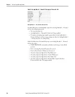
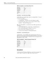
Table 327 - Analog Module 2 – Channel 00 Warning Level (Parameter 476)
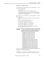
Analog Module 2 – Channel 01 Over Level Trip
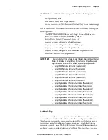
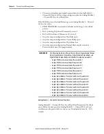
The E300 Electronic Overload Relay trips with an Analog Module 2 – Channel
01 Over Level Trip indication if:
•
No trip currently exists
•
Analog Module 2 – Channel 01 Over Level Trip is enabled
•
The measured analog input signal is greater than the Analog Module 2 –
Channel 01 Trip Level for a time period greater than the Analog Module 2
– Channel 01 Over Level Trip Delay.
If the E300 Electronic Overload Relay trips on an Analog Module 2 – Channel
01 Over Level, the:
•
TRIP/WARN LED status indicator flashes a red 4-long / 5-short blink
pattern
•
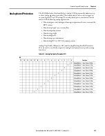
Bit 1 in Analog Trip Status (Parameter 8) sets to 1
•
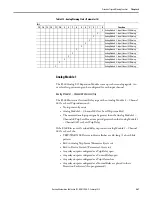
Bit 4 in Device Status 0 (Parameter 20) sets to 1
•
Any relay outputs configured as a Trip Relay open
•
Any relay outputs configured as a Control Relay open
•
Any relay outputs configured as a Trip Alarm close
•
Any relay outputs configured as a Normal Relay are placed in their
Protection Fault state (if so programmed)
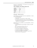
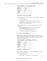
Default Value
0
Minimum Value
-32768
Maximum Value
32767
Parameter Type
INT
Size (Bytes)
2
Scaling Factor
1
Units
Summary of Contents for Allen-Bradley E300
Page 1: ...E300 Electronic Overload Relay Bul 193 592 User Manual...
Page 128: ...128 Rockwell Automation Publication 193 UM015D EN P February 2015 Chapter 5 Operating Modes...
Page 304: ...304 Rockwell Automation Publication 193 UM015D EN P February 2015 Chapter 7 Commands Notes...
Page 502: ...502 Rockwell Automation Publication193 UM015D EN P November 2013 Appendix B Parameter List...
Page 545: ......

