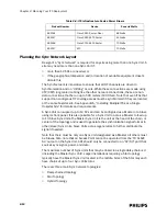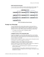
Planning the Sync Network Layout
IntelliVue Telemetry System Infrastructure Installation and Service Guide
2
-
15
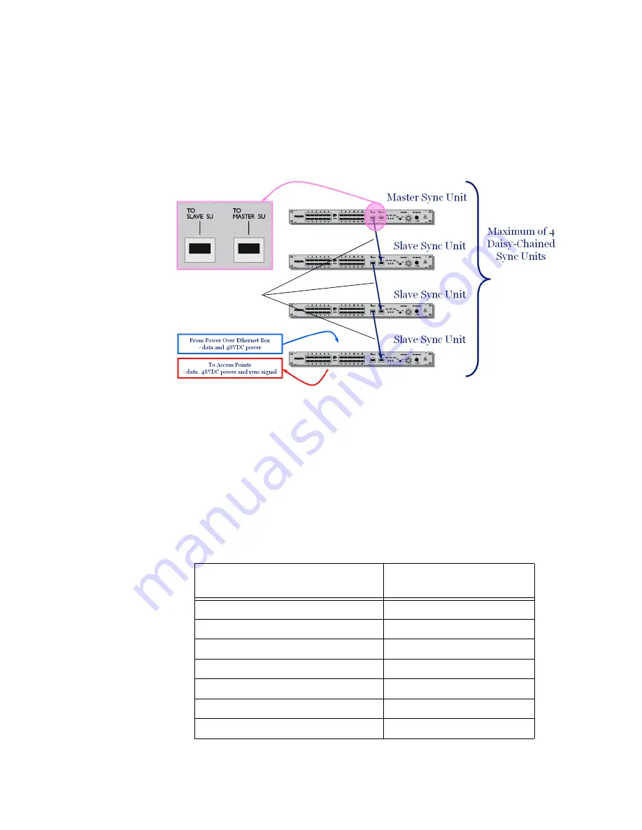
Daisy-chained Topology
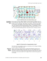
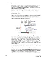
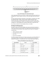
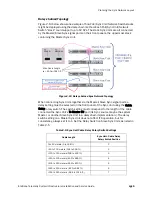
Figure 2-13 below shows one example of how PoE/Sync Unit/Network Switch stacks
might be deployed using the daisy-chain method. Each PoE/Sync Unit/Network
Switch “stack” could support up to 12 APs. The stack Sync Units are all connected
by the Master/Slave Sync signal ports on their front panels, the uppermost stack
containing the Master Sync Unit.
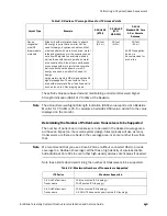
When connecting Sync Units together via the Master/Slave Sync signal ports, a
delay setting must be selected on the front panel of the Sync Unit using the Cable
Delay rotary switch. The switch setting must correspond to the length of the cable
connected the Sync Unit’s To Master SU port (its Sync source may be the system
Master, or another Slave Sync Unit in a daisy-chain implementation.). The delay
switch setting on a Master Sync Unit does not affect ITS operation, but for
consistency, always set it to 1. Set the Delay Switch on Slave Sync Units as listed in
Table 2-5.
Figure 2-13: Daisy-chained Sync Network Topology
Table 2-5: Sync Unit Cable Delay Rotary Switch Settings
Cable Length
Sync Unit - Cable Delay
Rotary Switch Position
0 to 50 meters (0 to 164 ft.)
1
>50 to 100 meters (164 to 328 ft.)
2
>100 to 150 meters (328 to 492 ft.)
3
>150 to 200 meters (492 to 656 ft.)
4
>200 to 250 meters (656 to 820 ft.)
5
>250 to 300 meters (821to 984 ft.)
6
>300 to 350 meters (984 to 1148 ft.)
7
Max. Cable Length
is < 500m (1640 ft.)
Summary of Contents for IntelliVue Telemetry System Infrastructure
Page 8: ...viii Contents ...
Page 14: ...xiv About This Guide ...
Page 100: ...3 22 Chapter 3 Installing and Configuring the ITS Figure 3 10 APC Filter Configuration Screen ...
Page 162: ...5 12 Chapter 5 Troubleshooting and Testing ...
Page 168: ...A 6 Chapter A Installing Multiple ITSs at a Single Hospital Site ...
Page 180: ...Index 8 Index ...

