1-4
Chapter 1: Overview
Philips provides Standard ITS Access Points for the 1.4 GHz US Wireless Medical
Telemetry Service (WMTS) band (P/N 862113) and the 2.4 GHz band for
deployments outside of the US (P/N 862232).
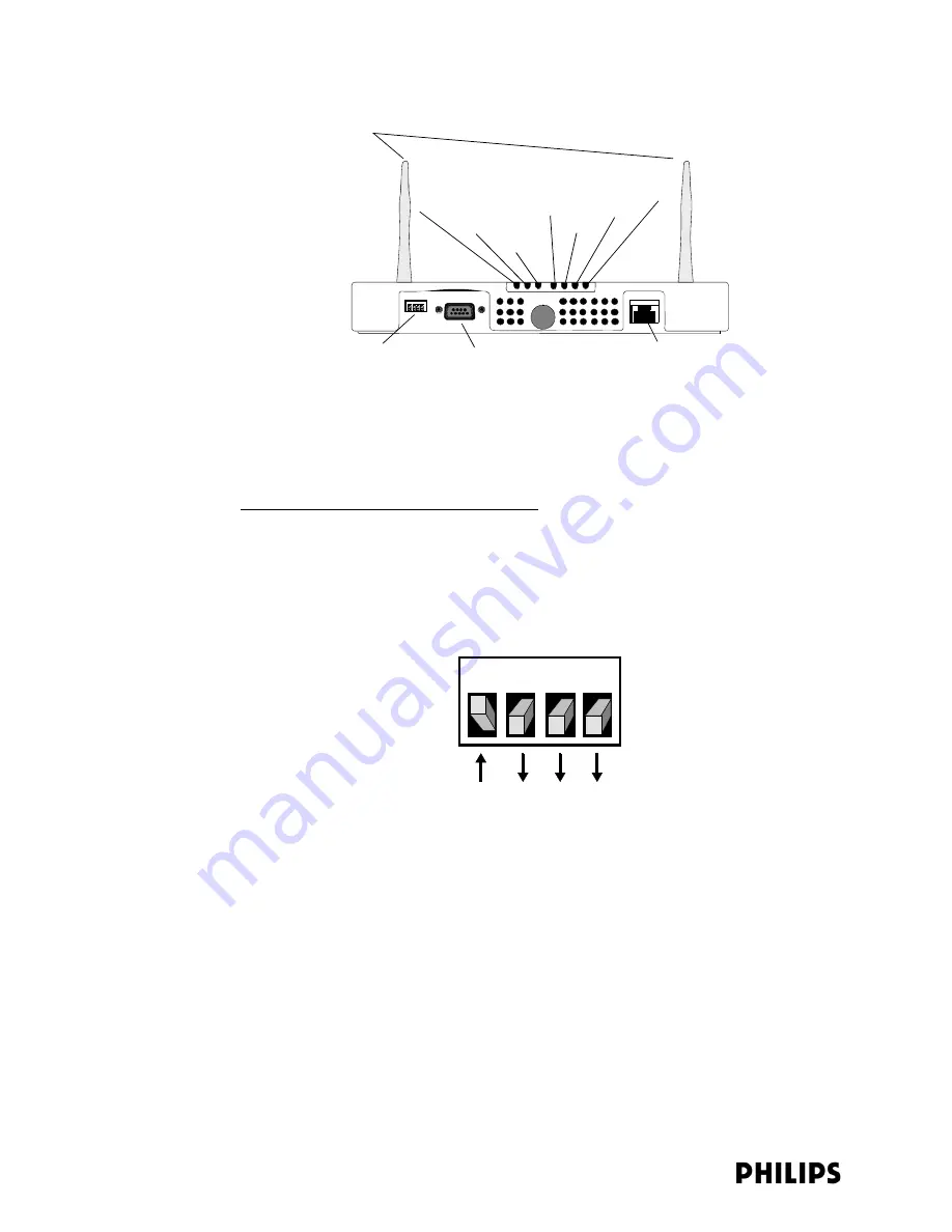
ITS Standard AP Controls and Connectors
Note the following controls and connectors on the ITS Standard Smart-hopping AP:
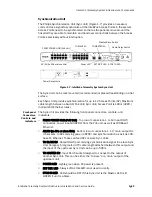
• Ethernet Dual Inline Package (DIP) Switches - These four switches that are
accessible from the outside of the AP case are used to enable manual selection
of Ethernet link options. The switch settings should
always
be set as indicated
in Figure 1-3.
• Serial Port - The serial port is used only for manufacturing purposes.
• Ethernet Interface - The AP provides a 100 Base-T Ethernet interface with an
RJ-45 connector to connect the AP to the ITS Sync Unit.
The AP Ethernet interface provides data communications to and from the
IntelliVue Information Center over the ITS LAN infrastructure. It also presents
the 48Vdc power and synchronization signals required by the AP. The
synchronization signal is superimposed on the power supply voltage. You must
attach a ferrite block to the CAT 5 cabling (from the Sync Unit) no more than 20
inches (50 cm) from the RJ-45 connector to reduce electromagnetic (radiation)
interference. Table 1-1 lists the pin signals for the AP Ethernet interface.
Figure 1-2: IntelliVue Telemetry System Standard Access Point
Figure 1-3: Required AP DIP Switch Settings
Antennas
Ethernet DIP Switches
Serial Port (Not Used)
100 Base-T Ethernet Interface
with RJ-45 Connector
Power/Sync
Network
Radio
FDX
100M
Link
ACT
Status LEDs
1 2 3 4
Summary of Contents for IntelliVue Telemetry System Infrastructure
Page 8: ...viii Contents ...
Page 14: ...xiv About This Guide ...
Page 100: ...3 22 Chapter 3 Installing and Configuring the ITS Figure 3 10 APC Filter Configuration Screen ...
Page 162: ...5 12 Chapter 5 Troubleshooting and Testing ...
Page 168: ...A 6 Chapter A Installing Multiple ITSs at a Single Hospital Site ...
Page 180: ...Index 8 Index ...


