General Intellivue Telemetry System Data Flow
IntelliVue Telemetry System Infrastructure Installation and Service Guide
1
-
13
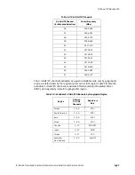
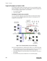
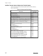
Refer Table 1-4 to when connecting ITS infrastructure devices to the UPS to ensure
that you do not exceed the UPS’ backup power capacity.
General Intellivue Telemetry System Data Flow
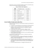
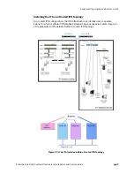
Data sent from the ITS transceiver to the IntelliVue Information Center traverses the
network as follows:
1. The transceiver sends its ECG data over the wireless link to an ITS Access Point.
2. The AP then “wraps” the ECG data into another message packet, with its
destination as the Access Point Controller that is assigned to handle the
management activities for that AP.
3. The wired network then treats the packet like a message to the APC.
4. The APC receives the packet, “unwraps” it and determines that the message is
for the IntelliVue Information Center.
5. The APC repackages the message and forwards it on with a destination address
of the IntelliVue Information Center.
Data sent from the IntelliVue Information Center to a patient-worn transceiver
traverses the network as follows:
1. The Information Center sends a message to the transceiver’s IP address. The
network “sees” the location of the transceiver’s IP address as the location of
the APC, and sends the message there.
2. The APC then looks at the message, determines which ITS Access Point is
currently connected to the transceiver it needs to send the message to, “wraps”
the message into a packet and forwards the packet on to the appropriate ITS
Access Point.
3. The network handles the packet as a message for the ITS Access Point.
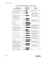
Table 1-4: ITS Device Power Requirements
Product
Number
ITS Infrastructure Device
Power in Watts
862114
Sync Unit
10 Watts
862152
PoE Unit – 12 Port
165 Watts
862149
PoE Unit – 6 Port
90 Watts
862161
Cisco 2950 Switch: Copper
30 Watts
862162
Cisco 2950 Switch: Fiber
30 Watts
862084
HP 2524 Switch
36 Watts
862163
Cisco 3550 Router: Copper
65 Watts
862164
Cisco 3550 Router: Fiber
85 Watts
862147
APC
10 Watts
Summary of Contents for IntelliVue Telemetry System Infrastructure
Page 8: ...viii Contents ...
Page 14: ...xiv About This Guide ...
Page 100: ...3 22 Chapter 3 Installing and Configuring the ITS Figure 3 10 APC Filter Configuration Screen ...
Page 162: ...5 12 Chapter 5 Troubleshooting and Testing ...
Page 168: ...A 6 Chapter A Installing Multiple ITSs at a Single Hospital Site ...
Page 180: ...Index 8 Index ...


