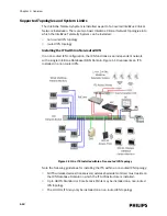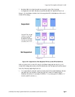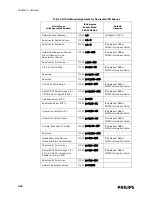
IntelliVue Telemetry System Infrastructure Components
IntelliVue Telemetry System Infrastructure Installation and Service Guide
1
-
5
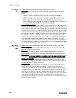
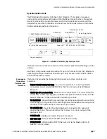
Standard AP Status LEDs
The ITS Standard Smart-hopping AP provides seven status LEDs.
• Wireless/RF Activity - The AP provides three LEDs to indicate wireless/RF
activity. During normal operation, these LEDs indicate the following information:
- Power/Sync LED - GREEN (ON) when power and synchronization signal is
present.
- Network LED - Normally OFF (not lit) - flashes green to indicate network
activity.
- Radio LED - Normally OFF (not lit) - flashes green to indicate network activity.
For 2.4 GHz standard APs, the three LEDs above can be viewed from the APC
web interface.
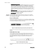
At initial power on the AP runs a Power On Self-Test (POST). During the POST, the
above LED indicators flicker and then all three will illuminate continuously
(AMBER) to indicate correct startup operation. Then, the Power ON LED will
illuminate (GREEN) continuously to indicate that the 48Vdc power and sync
signal are being supplied, and the other two (AMBER) LEDs turn off (not lit).
• Wired/Ethernet Activity - The AP provides four LEDs to indicate wired/Ethernet
activity. During normal operation, these LEDs indicate the following information:
- Act LED - Transmit activity. Flashes GREEN (ON) when there is activity is over
the wired network.
- Link LED - Link present/Ethernet connection. Lights GREEN (ON) when a
pass-through link is present - OFF when not present.
- 100M LED - Link Speed. Lights GREEN (ON) (GOOD) for a 100 Base-T
(100Mbps) connection - OFF (not lit) (BAD) for a 10 Base-T connection.
- FDX LED - Receive activity. Lights GREEN (ON) (GOOD) to indicate Full Duplex
connection. OFF (not lit) indicates Half Duplex connection (BAD).
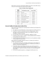
Table 1-1: AP Ethernet Interface Pin Signals
Pin
Signal Description
1
Transmit Pair TX + Conductor
2
Transmit Pair TX - Conductor
3
Receive Pair RX + Conductor
4
+ 48Vdc Power and Synchronization
5
+ 48Vdc Power and Synchronization
6
Receive Pair RX - Conductor
7
0V Power Return
8
0V Power Return
Summary of Contents for IntelliVue Telemetry System Infrastructure
Page 8: ...viii Contents ...
Page 14: ...xiv About This Guide ...
Page 100: ...3 22 Chapter 3 Installing and Configuring the ITS Figure 3 10 APC Filter Configuration Screen ...
Page 162: ...5 12 Chapter 5 Troubleshooting and Testing ...
Page 168: ...A 6 Chapter A Installing Multiple ITSs at a Single Hospital Site ...
Page 180: ...Index 8 Index ...


