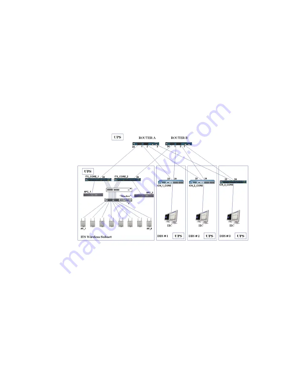
Sample Routed Topology
IntelliVue Telemetry System Infrastructure Installation and Service Guide
B
-
3
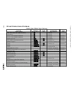
Refer to Table B-1 for a list of the device IP address assignments used in a routed
ICN configuration where the ITS infrastructure is installed as a separate subnet to
which up to 22 Database Domains have access via routers.
Note the following regarding Table B-1:
• “n” represents the network number and starts at 0 for single ICN Database
Domains. This variable increments by 8 from there for additional ICN database
Domains. For example, for DBS 2, “n” would equal 8, for DBS 3, “n” would equal
16, and so on.
• Route statements are generated (in instances with a Router and without) at the
completion of the Config Wizard.
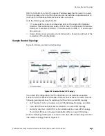
Sample Routed Topology
Figure B-1 shows a sample routed topology.
In a routed ICN configuration, the ITS infrastructure is installed as a separate
subnet to which multiple ICN Database Domains have access via routers. Note the
following general guidelines for installing the ITS within a routed ICN topology:
• An ITS subnet can be connected up to 22 ICN Database Domains via routers.
• Up to 320 ITS Access Points may be installed on a routed ICN topology.
• Currently, only the 1.4 GHz ITS may be installed within a routed ICN topology.
The 2.4 GHz ITS does not support installation within a routed ICN topology.
Note the following possible port connections and device IP address assignments for
this sample topology shown in Figure B-1:
Figure B-1: Sample Routed ITS Topology
Summary of Contents for IntelliVue Telemetry System Infrastructure
Page 8: ...viii Contents ...
Page 14: ...xiv About This Guide ...
Page 100: ...3 22 Chapter 3 Installing and Configuring the ITS Figure 3 10 APC Filter Configuration Screen ...
Page 162: ...5 12 Chapter 5 Troubleshooting and Testing ...
Page 168: ...A 6 Chapter A Installing Multiple ITSs at a Single Hospital Site ...
Page 180: ...Index 8 Index ...

