136
Outline of Functions
Section 4-2
4-2
Outline of Functions
4-2-1
NT20 Screen
This section gives the outline of the screen which is the basis of all NT20 func-
tions.
For specific operation procedure such as screen switching, refer to
5-1-4
Switching the Screen Display
(page 172).
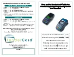
Composition of the Screen
The NT20 screen is composed of horizontal 256 dots x vertical 128 dots.
Each dot is set by the combination of the X (horizontal) and Y (vertical) coordi-
nates. The origin of coordinates (0, 0) is set at the top left corner of the
screen.
Screen Management
The screens displayed on the NT20 are managed by the screen numbers.
When using the NT20, up to 495 screens can be created and screen numbers
in the ranges 1 to 250 and 256 to 500 can be used (numbers 251 to 255 are
reserved for system use).
The display screens can be switched or the start-up screen can be set by des-
ignating the screen number from the Host.
Special Screen Number
Screen number “0” is reserved for the system as the no-display screen. Select
this to display nothing on the NT20 screen.
X coordinate (horizontal)
Y coordinate
(vertical)
Coordinates
(x, y)
255
255, 127
127
0
0
Summary of Contents for NT20
Page 1: ...Programmable Terminal Cat No V091 E1 01 NT20 USER S MANUAL ...
Page 2: ...NT series Programmable Terminal User s Manual Produced March 2007 ...
Page 3: ...iv ...
Page 5: ...vi ...
Page 9: ...x TABLE OF CONTENTS ...
Page 15: ...xvi ...
Page 21: ...xxii EC Directives 6 ...
Page 37: ...16 Before Operating Section 1 6 ...
Page 153: ...132 Transferring the Resource Data Section 3 11 ...
Page 185: ...164 Numeral Setting Section 4 8 ...
Page 267: ...246 Key to Programs Section 6 8 ...
Page 281: ...260 Specifications Appendix A ...
Page 285: ...264 Transporting and Storing PTs Appendix C ...
Page 303: ...282 Function Restrictions Depending on the Support Tool Appendix I ...
Page 307: ...286 Index ...
Page 309: ...288 Revision History ...