196
Lamps, Touch Switches, Numeral Setting
Section 5-3
5-3-5
Notifying the Host That a Switch Has Been Pressed
(Determining Touch Switch Status)
This section describes how the status of a touch switch (whether it has been
pressed or not) is ascertained.
With the NT20, when a touch switch is pressed, the notify bit allocated to that
touch switch in the PLC memory is automatically updated.
Depending on the set operation type, the status of the allocated bit for touch
switch status notification will be controlled in one of the following ways:
Momentary:
0 (OFF) ... Not pressed
1 (ON) ... Pressed
Alternate:
The allocated bit is switched to 1 (ON) if currently 0, and
to 0 (OFF) if currently 1.
Set:
The allocated notify bit is forcibly switched to 1 (ON).
Reset:
The allocated notify bit is forcibly switched to 0 (OFF).
In order to determine the status of a touch switch, the status of the touch
switch notification bit allocated to it is determined.
The touch switch notify bits can be allocated to the following areas of the PLC
memory.
❍
: OK
×
: NG
Since all the CVM1/CV-series AR area bits are allocated to the system, they
cannot be used for applications not related to the system.
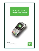
Touch switch #1
Allocated notify bit (touch switch #1)
NT20
PLC
1
Symbol
C-series
Alloca-
tion
CVM1/CV -series
Alloca-
tion
CS/CJ-series
Alloca-
tion
None
IR Area
❍
CIO Area
❍
CIO Area
❍
H
HR Area
❍
---
---
HR Area
Not for
Host Link
A
AR Area
❍
AR Area
×
AR Area
❍
L
LR Area
❍
---
---
LR Area (See note 1.)
Not for
Host Link
T
TC Area
Timer PVs
×
TC Area
Timer PVs
×
TC Area
Timer PVs
×
TU
---
---
---
---
TC area,
Timer Completion Flags
×
C
TC Area
Counter PVs
×
TC Area
Counter PVs
×
TC Area
Counter PVs
×
CU
---
---
---
---
TC area,
Counter Completion Flags
×
W
---
---
---
---
WR
Not for
Host Link
TK
---
---
---
---
Task Flags
×
D
DM Area
❍
DM Area
❍
DM Area
❍
E
EM Area
(See note 2.)
❍
EM Area
Current bank
Not for
Host Link
EM Area
Current bank
Not for
Host Link
E0_to EC_
---
---
---
---
EM Area
EM bank 0 to C
Not for
Host Link
Summary of Contents for NT20
Page 1: ...Programmable Terminal Cat No V091 E1 01 NT20 USER S MANUAL ...
Page 2: ...NT series Programmable Terminal User s Manual Produced March 2007 ...
Page 3: ...iv ...
Page 5: ...vi ...
Page 9: ...x TABLE OF CONTENTS ...
Page 15: ...xvi ...
Page 21: ...xxii EC Directives 6 ...
Page 37: ...16 Before Operating Section 1 6 ...
Page 153: ...132 Transferring the Resource Data Section 3 11 ...
Page 185: ...164 Numeral Setting Section 4 8 ...
Page 267: ...246 Key to Programs Section 6 8 ...
Page 281: ...260 Specifications Appendix A ...
Page 285: ...264 Transporting and Storing PTs Appendix C ...
Page 303: ...282 Function Restrictions Depending on the Support Tool Appendix I ...
Page 307: ...286 Index ...
Page 309: ...288 Revision History ...