69
CX-Programmer Procedures
Section 4-12
2.
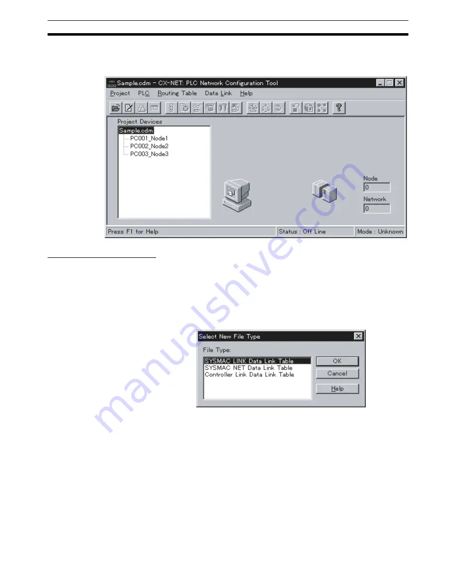
Open the CX-Server file (*.CDM) in CX-Net or create a new file in CX-Net
by selecting
Project
and then
Open
in CX-Net. In this example, Sam-
ple.cdm is used as the file name.
The following dialog box will be displayed.
Creating Data Link Tables
Create the data link tables for each node entered in the CX-Server file. In this
example, the data link tables are created automatically using the Data Link
Table Engineer, then the parameters are changed manually.
Starting the Data Link Editor
1,2,3...
1.
Select
Data Link
and then
Editor
. A dialog box for selecting the type of
data link will appear.
2.
Select
SYSMAC LINK Data Link Table
and then click the
OK
button. The
Data Link Editor [SYSMAC LINK] will start.
Making Manual Settings
without Using the Data
Link Table Engineer
You can make Manual Settings without using the Data Link Table Engineer.
Create data link tables manually in the following cases.
• The send area size is different for each node participating in the data link.
• The send node order is not the same as the order of node addresses.
• There are nodes that are not receiving data.
Summary of Contents for CS1W-SLK11-21 - 06-2004
Page 1: ...Cat No W367 E1 02 SYSMAC CS1W SLK11 21 SYSMAC LINK Units...
Page 2: ...CS1W SLK11 21 SYSMAC LINK Units Operation Manual Revised June 2004...
Page 3: ...iv...
Page 5: ...vi...
Page 9: ......
Page 11: ......
Page 17: ......
Page 49: ......
Page 107: ......
Page 139: ...122 FINS Commands for SYSMAC LINK Units Section 6 4...
Page 143: ......
Page 170: ...153 Appendix B Dimensions CS1W SLK11 Optical SYSMAC LINK Unit Unit mm...
Page 171: ...154 Dimensions Appendix B CS1W SLK21 Coaxial SYSMAC LINK Unit Unit mm...
Page 177: ......
Page 179: ......
Page 195: ......
Page 199: ......
Page 202: ...SYSMAC CS1W SLK11 21 SYSMAC LINK Units Cat No W367 E1 02 OPERATION MANUAL...


