616
Chapter 15
Asynchronous Serial Interface C (UARTC)
User’s Manual U16580EE3V1UD00
(4)
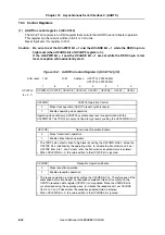
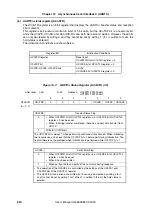
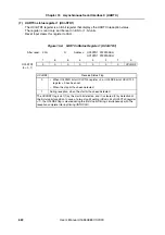
UARTCn option control register 0 (UCnOPT0)
The UCnOPT0 register is an 8-bit register that controls the serial transfer operation of the
UARTCn register.
This register can be read or written in 8-bit or 1-bit units.
Reset input sets this register to 14H.
Figure 15-5:
UARTCn Option Control Register 0 (UCnOPT0) (1/2)
After reset:
14H
R/W
Address:
UC0OPT0 FFFFFA03H,
UC1OPT0 FFFFFA23H
7
6
5
4
3
2
1
0
UCnOPT0
UCnSRF
UCnSRT
UCnSTT UCnSLS2 UCnSLS1 UCnSLS0 UCnTDL
UCnRDL
(n = 0, 1)
UCnSRF
SBF Reception Flag
0
When UCnPWR of UCnCTL0 register = 0 and UCnRXE of UCnCTL0
register = 0 are set. Also upon normal end of SBF reception.
1
During SBF reception
•
SBF (Sync Brake Field) reception is judged during LIN communication.
•
The UCnSRF bit is held high when a SBF reception error occurs, and then SBF
reception is started again.
UCnSRT
SBF Reception Trigger
0
–
1
SBF reception trigger
•
This is the SBF reception trigger bit during LIN communication, and when read, “0” is
always read. For SBF reception, set the UCnSRT bit (to 1) to enable reception.
•
Set the UCnSRT bit after setting the UCnPWR bit of the UCnCTL0 register to 1 and
the UCnRXE bit of the UCnCTL0 register to 1.
UCnSTT
SBF Transmission Trigger
0
–
1
SBF transmission trigger
•
This is the SBF transmission trigger bit during LIN communication, and when read, “0”
is always read.
•
Set the UCnSRT bit after setting the UCnPWR bit of the UCnCTL0 register to 1 and
the UCnRXE bit of the UCnCTL0 register to 1.
Summary of Contents for V850E/PH2
Page 6: ...6 Preface User s Manual U16580EE3V1UD00...
Page 16: ...16 User s Manual U16580EE3V1UD00...
Page 28: ...28 User s Manual U16580EE3V1UD00...
Page 32: ...32 User s Manual U16580EE3V1UD00...
Page 84: ...84 Chapter 2 Pin Functions User s Manual U16580EE3V1UD00 MEMO...
Page 144: ...144 Chapter 3 CPU Functions User s Manual U16580EE3V1UD00 MEMO...
Page 192: ...192 Chapter 5 Memory Access Control Function PD70F3187 only User s Manual U16580EE3V1UD00 MEMO...
Page 312: ...312 Chapter 9 16 Bit Timer Event Counter P User s Manual U16580EE3V1UD00 MEMO...
Page 534: ...534 Chapter 11 16 bit Timer Event Counter T User s Manual U16580EE3V1UD00...
Page 969: ...969 Chapter 20 Port Functions User s Manual U16580EE3V1UD00 MEMO...
Page 970: ...970 Chapter 20 Port Functions User s Manual U16580EE3V1UD00...
Page 976: ...976 Chapter 22 Internal RAM Parity Check Function User s Manual U16580EE3V1UD00 MEMO...
Page 984: ...984 Chapter 23 On Chip Debug Function OCD User s Manual U16580EE3V1UD00 MEMO...
Page 1006: ...1006 Chapter 24 Flash Memory User s Manual U16580EE3V1UD00 MEMO...
Page 1036: ...1036 Chapter 27 Recommended Soldering Conditions User s Manual U16580EE3V1UD00 MEMO...
Page 1046: ...1046 Appendix A Index User s Manual U16580EE3V1UD00 MEMO...
Page 1052: ...1052 User s Manual U16580EE3V1UD00...
Page 1053: ......

