Disassembly and Reassembly 3-9
4.
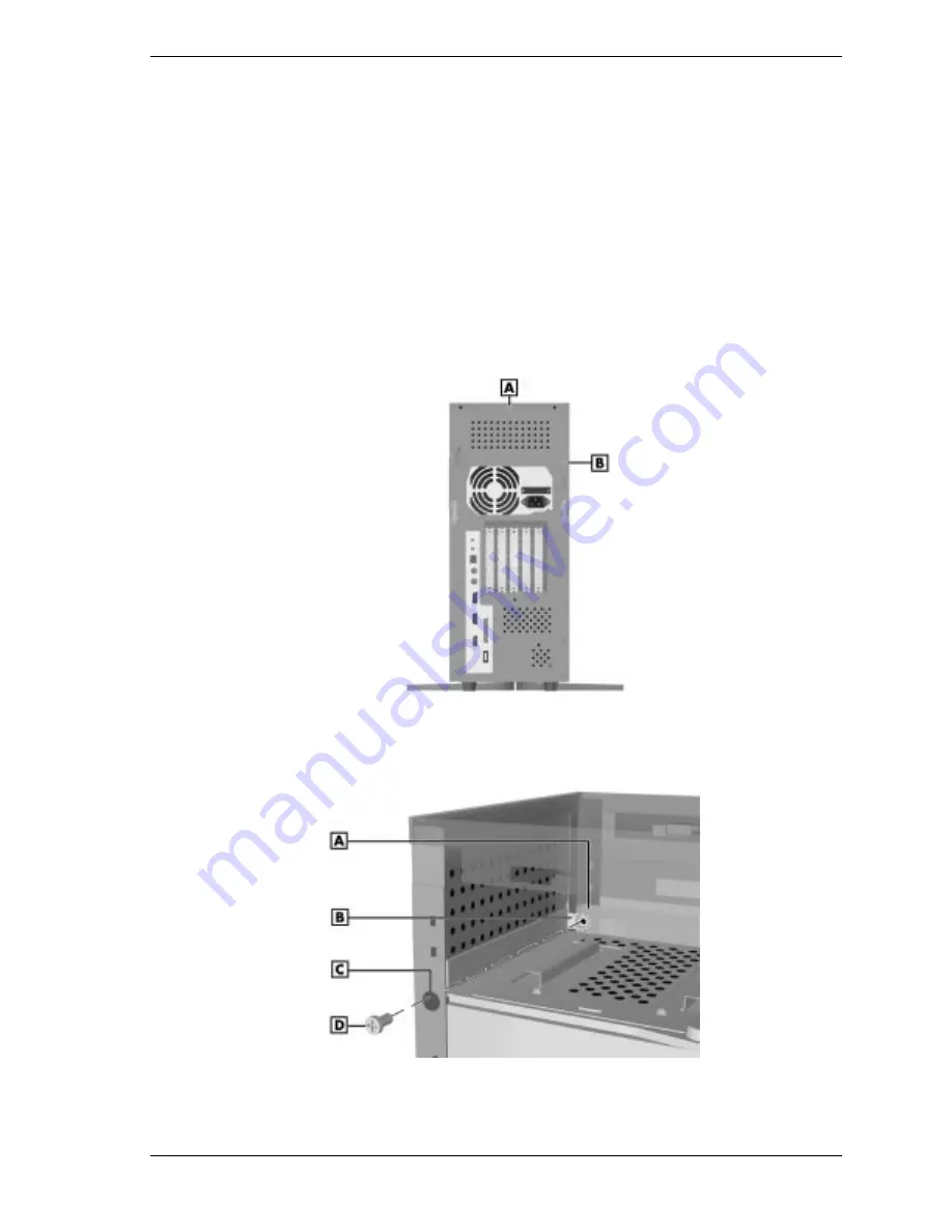
Remove the screw securing the cover to the chassis.
For the left side cover, remove the screw securing the back edge of the
cover to the chassis (see the following figure).
For the right side cover, remove the screw inside the system that secures
the right cover tab to the chassis bracket (see the second figure below).
Position the screwdriver through the hole in the back left edge of the
chassis to gain access to the screw.
If necessary, remove the hard drive bracket to access to the right side
cover screw (see “Removing a 3 1/2-Inch Hard Drive — Minitower”).
Locating the Top and Left Side Cover Screws — Minitower
A – Top Cover Screw
B – Left Side Cover Screw
Locating the Right Side Cover Screw — Minitower
A – Chassis Bracket
C – Screwdriver Hole
B – Right Side Cover Tab
D – Screw
Summary of Contents for POWERMATE ES 5200 - SERVICE
Page 18: ...1 System Overview Configurations Features Components ...
Page 168: ...4 System Board Connectors Jumpers and Sockets Components Resources ...
Page 222: ...7 Preventive Maintenance System Cleaning Keyboard Cleaning Mouse Cleaning ...
Page 226: ...8 Troubleshooting Checklist Diagnostics ...
Page 300: ...Regulatory Statements FCC Statement Note for Canada Battery Replacement Battery Disposal ...


