Disassembly and Reassembly 3-35
3.
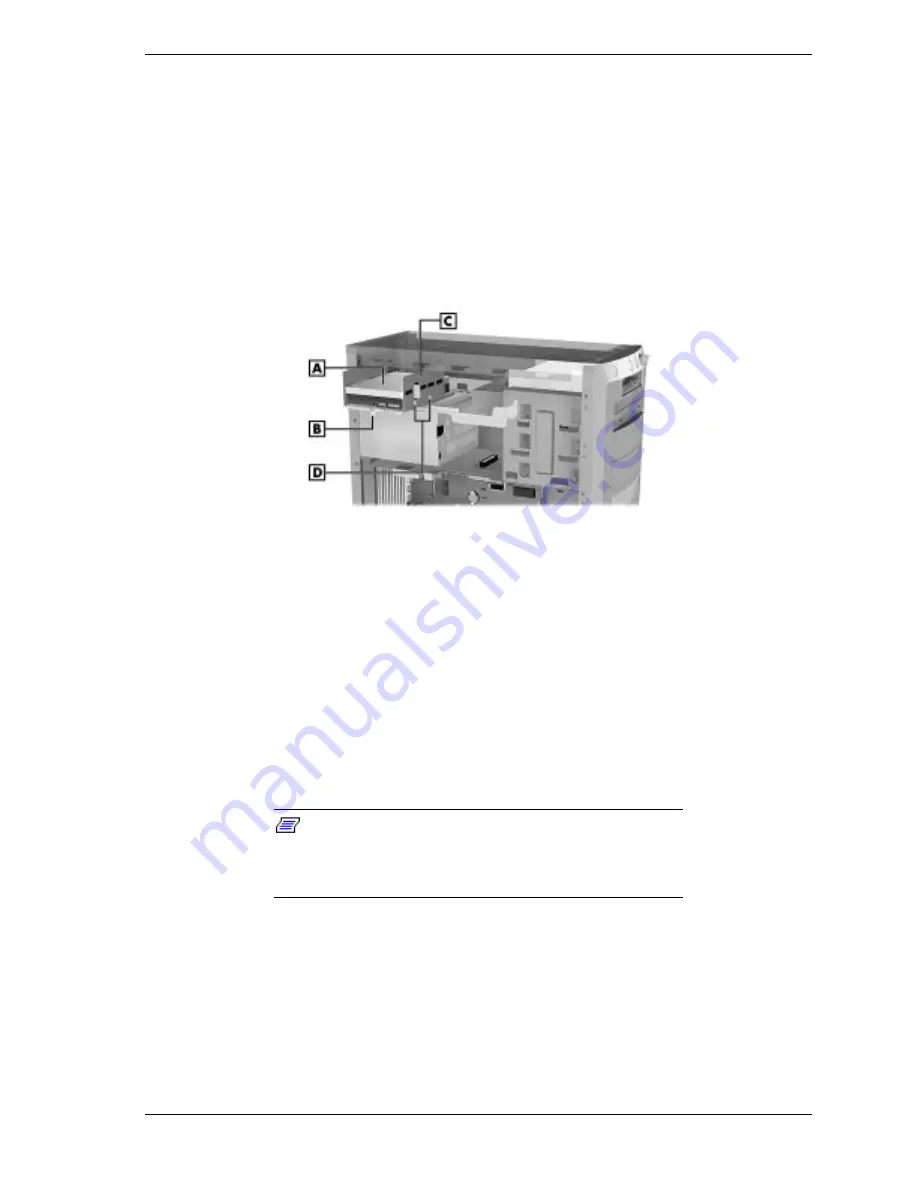
Press down on the latch securing the drive bracket to the chassis and pull the
bracket out of the chassis (see the following figure). Pull the bracket out
only far enough to access the drive mounting screws and cable connectors.
4.
Label and disconnect the IDE drive signal and power cables from the hard
drive.
5.
Remove the four screws (two to a side) securing the drive to the drive
bracket.
Locating the Hard Drive Bracket and Screws — Minitower
A – Hard Drive
C – Drive Bracket
B – Latch
D – Screws (2 to a side)
6.
Remove the drive from the drive bracket.
7.
If you are installing a new hard drive, see “Installing a 3 1/2-Inch Hard
Drive — Minitower.”
Installing a 3 1/2-Inch Hard Drive — Minitower
You can upgrade your system by replacing an existing hard drive or by adding a
second drive. Hard drive(s) install in an internal drive bracket located at the top
rear of the chassis.
Note:
You can also install a 3 1/2-inch hard drive in
a 5 1/4-inch accessible device bay. Place the device in a
5 1/4-inch frame adapter and then follow the instructions in
“Installing a 5 1/4-Inch Device — Minitower.”
To install a 3 1/2-inch internal hard drive in the system, proceed as follows.
1.
Follow the preinstallation instructions that come with your device, such as
setting jumpers.
2.
Remove the left side cover (see “Removing the Minitower Side Covers”).
3.
Remove the top cover (see “Removing the Minitower Top Cover”).
Summary of Contents for POWERMATE ES 5200 - SERVICE
Page 18: ...1 System Overview Configurations Features Components ...
Page 168: ...4 System Board Connectors Jumpers and Sockets Components Resources ...
Page 222: ...7 Preventive Maintenance System Cleaning Keyboard Cleaning Mouse Cleaning ...
Page 226: ...8 Troubleshooting Checklist Diagnostics ...
Page 300: ...Regulatory Statements FCC Statement Note for Canada Battery Replacement Battery Disposal ...


