3-14 Disassembly and Reassembly
5.
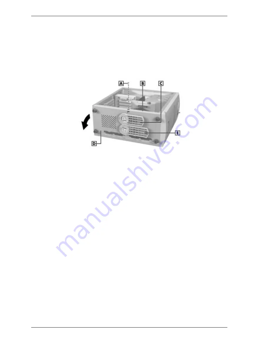
Grasp the top edge of the chassis floor and pull down to open the floor.
Opening the chassis floor also unplugs the system board from its connector
on the riser board.
6.
Grasp the two board handles and pull the board out further if you cannot
access to the components you are upgrading. If you need to replace the
board, see “Removing the System Board — Minitower” later in this section.
Releasing the Chassis Floor — Minitower
A – Screw
D – Chassis Floor
B – Top Edge of Chassis Floor
E – Right Chassis Foot
C – Left Chassis Foot
Closing the Chassis Floor
To close the chassis floor, proceed as follows.
1.
If the system board was partially slid out for access to board components,
slide it back into the chassis using the two board handles.
If the system board was removed, see “Installing the System Board —
Minitower” for replacement procedures.
2.
Pivot the floor up against the chassis and press until the floor latches in
place. Closing the floor also plugs the system board into the riser board.
3.
Secure the floor to the chassis with the previously removed screw.
4.
Place the system unit upright and swivel the two chassis feet out,
perpendicular to the system unit.
5.
Replace the left side cover (see “Replacing the Minitower Side Covers”).
Summary of Contents for POWERMATE ES 5200 - SERVICE
Page 18: ...1 System Overview Configurations Features Components ...
Page 168: ...4 System Board Connectors Jumpers and Sockets Components Resources ...
Page 222: ...7 Preventive Maintenance System Cleaning Keyboard Cleaning Mouse Cleaning ...
Page 226: ...8 Troubleshooting Checklist Diagnostics ...
Page 300: ...Regulatory Statements FCC Statement Note for Canada Battery Replacement Battery Disposal ...


