Disassembly and Reassembly 3-19
Removing the Front Panel — Minitower
Remove the front panel before installing a device in a 5 1/4-inch accessible
device bay. You may also need to remove the blank panel that covers the bay on
the front panel and the metallic shield over the bay. The front panel does not
need to be removed if you are installing a diskette drive.
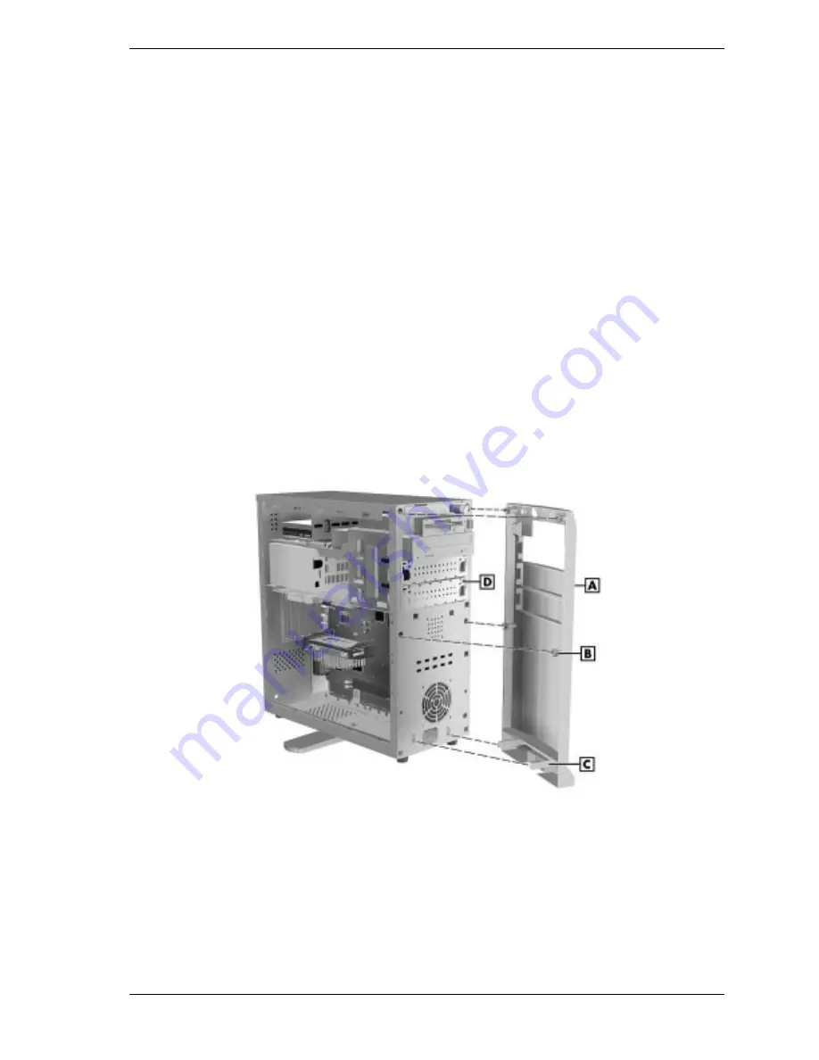
The front panel is attached to the chassis with locking tabs and plugs. The two
locking tabs are at the bottom inside corners of the cover and the four plugs are
at the middle and top of the cover. (See the following figure.)
To remove the front panel, proceed as follows.
1.
Remove the left side cover (see “Removing the Minitower Side Covers”).
2.
From inside the chassis, squeeze the two front panel locking tabs in the
lower left and right corners (see the following figure).
3.
Carefully push the tabs out until they release the bottom of the front panel.
4.
Grasp the side edges of the front panel. Carefully pull the front panel away
from the system unit until the four plugs release.
Locating the Front Panel Tabs and Plugs — Minitower
A – Front Panel
C – Locking Tab (1 of 2)
B – Pop-out Plug (1 of 4)
D – Bay Cover
5.
Identify the bay on the front panel for the device being installed.
6.
Remove the blank plastic panel from the selected bay by pressing the panel
tabs from inside the front panel and pushing the blank panel out (see the
figure on the following page).
Summary of Contents for POWERMATE ES 5200 - SERVICE
Page 18: ...1 System Overview Configurations Features Components ...
Page 168: ...4 System Board Connectors Jumpers and Sockets Components Resources ...
Page 222: ...7 Preventive Maintenance System Cleaning Keyboard Cleaning Mouse Cleaning ...
Page 226: ...8 Troubleshooting Checklist Diagnostics ...
Page 300: ...Regulatory Statements FCC Statement Note for Canada Battery Replacement Battery Disposal ...


