3-4 Disassembly and Reassembly
Note:
If the cover is removed, LANDesk Client Manager
logs the intrusion and reports it in a screen message the
next time the system is booted. This message appears every
time the system is rebooted until the report is cleared. For
more information on closing the notification window and
clearing the message, see “Using the Chassis Intrusion
Notification Feature” in Section 2.
1.
Turn off and unplug the system unit.
2.
Disconnect the keyboard, mouse, monitor, and any other external options
(such as speakers or a printer) from the rear of the system unit.
!
CAUTION
Electrostatic discharge can damage computer components.
Discharge static electricity by touching a metal object before
removing the system unit cover.
3.
Remove any lock or security cable (if one has been installed).
4.
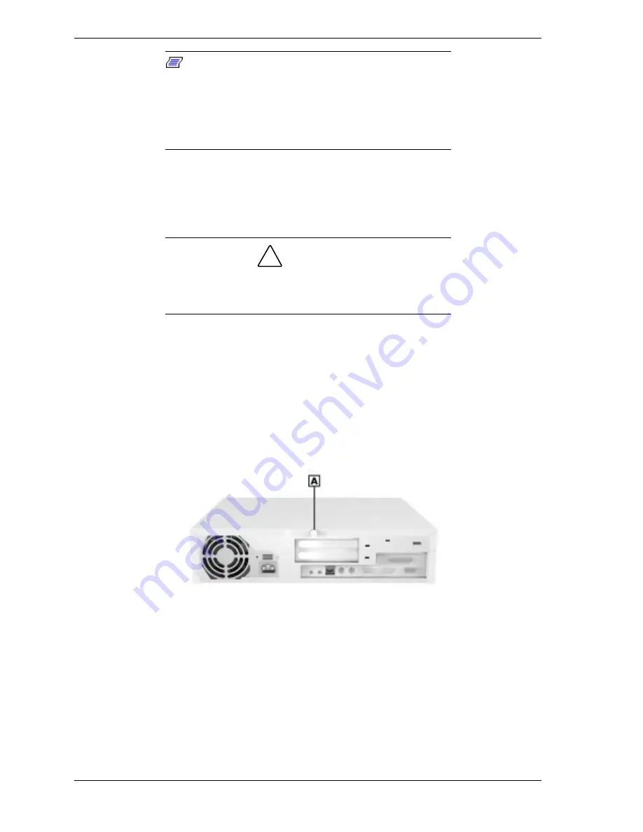
Remove the cover screw(s) on the rear of the system (see the following
figures).
For a small desktop system, remove the single screw.
For a desktop system, remove the two screws.
Locating the Cover Screw — Small Desktop
A – Cover Screw
Summary of Contents for POWERMATE ES 5200 - SERVICE
Page 18: ...1 System Overview Configurations Features Components ...
Page 168: ...4 System Board Connectors Jumpers and Sockets Components Resources ...
Page 222: ...7 Preventive Maintenance System Cleaning Keyboard Cleaning Mouse Cleaning ...
Page 226: ...8 Troubleshooting Checklist Diagnostics ...
Page 300: ...Regulatory Statements FCC Statement Note for Canada Battery Replacement Battery Disposal ...


