


Disassembly and Reassembly 3-61
4.
Slide the bracket about 1/4 inch toward the front of the chassis to free it
from the tabs on the chassis floor.
5.
Lift the internal drive bracket out of the system.
Removing the Additional Drive Bracket
You need to remove the drive bracket that houses the additional 3 1/2-inch drive
if you have to remove the riser board.
Remove the additional drive bracket by following these steps.
1.
If the system has a drive in the additional 3 1/2-inch drive bay, remove it
first (see “Removing the Additional 3 1/2-Inch Drive — Desktop”).
2.
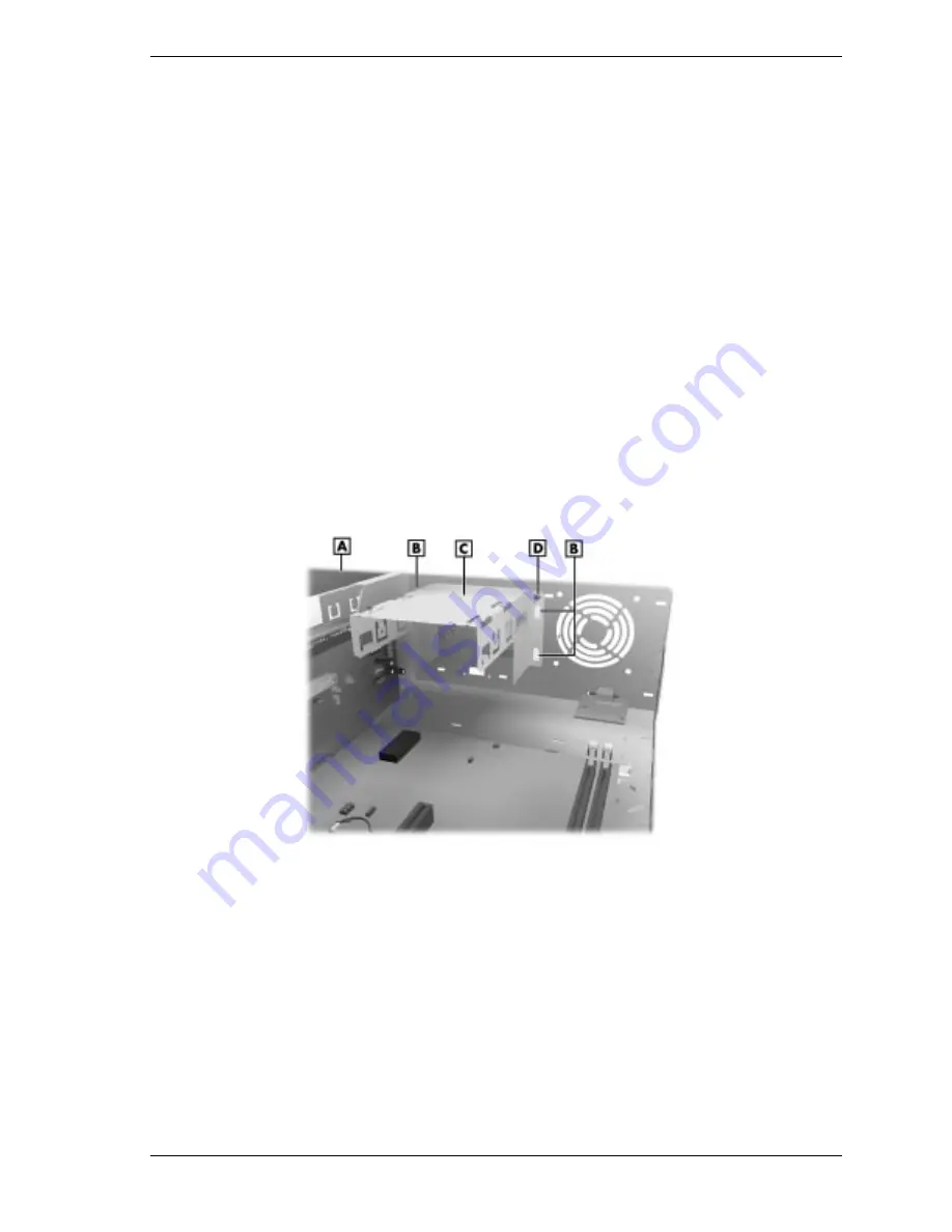
Remove the screw that holds the bracket to the front of the chassis (see the
following figure).
3.
Lift the bracket up slightly to free it from the four tabs on the chassis.
4.
Pull the bracket out of the system.
Locating the Additional Drive Bracket — Desktop
A – Front of Chassis
C – Additional 3 1/2-Inch Drive Bracket
B – Tabs
D – Screw
Summary of Contents for POWERMATE ES 5200 - SERVICE
Page 18: ...1 System Overview Configurations Features Components ...
Page 168: ...4 System Board Connectors Jumpers and Sockets Components Resources ...
Page 222: ...7 Preventive Maintenance System Cleaning Keyboard Cleaning Mouse Cleaning ...
Page 226: ...8 Troubleshooting Checklist Diagnostics ...
Page 300: ...Regulatory Statements FCC Statement Note for Canada Battery Replacement Battery Disposal ...


