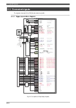
2.3 Connected signals
2-17
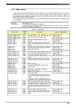
Input signal diagnosis
With input signal diagnosis, troubles caused by the input devices (short-circuit trouble, open-circuit trouble,
stuck-at faults, etc) are detected. The trouble in the input circuit is diagnosed by the diagnosis circuit so that it is
possible to reliably detect it when the input signals have been turned OFF.
If error has been detected by the input signal diagnosis, the "Internal error: Input diagnosis" and the "Internal
error: Input signal" result and the safety outputs are turned OFF. To release the error, power of this unit needs to
be turned OFF an ON.
Disparity diagnosis
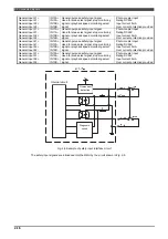
The safety input signals processed by the software operated inside the two CPUs are mutually checked
between the CPUs, and through this it is checked whether the logic is correct.
This diagnosis is conducted after the input signal diagnosis described above. If the logic fails to match
between the two inputs for a period in excess of 500 ms, the Input signal diagnosis error (unrecoverable error)
results, the safety outputs are turned OFF, and the unit’s power must be turned off and turned back on.
Remove the cause of the error and then press [Reset] key twice from teach pendant.
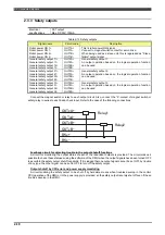
When an input signal has changed from ON to OFF
An error is identified if both signals (of the two systems) are not turned OFF within 500 ms.
When an input signal has changed from OFF to ON
An error is identified if both signals (of the two systems) are not turned ON or OFF within 500 ms.
Note: The ON-OFF change in a signal of less than 500 ms is ignored as signal noise.
If mismatch of enable switch signals (11, 12, 21, 22) is detected, the safety output will be turned OFF but the
error is not detected.
By turning OFF the enable switch one time, the error will be reset.
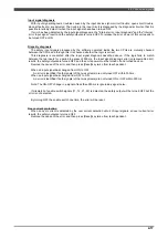
Over current protection
When an over current is detected by the over current detection circuit of input signals, an over current error
results, the safety outputs are turned OFF.
Remove the cause of the error and then press [Reset] key twice from teach pendant..
Summary of Contents for RMU20-20
Page 2: ......
Page 6: ...Contents 4 ...
Page 8: ......
Page 26: ...1 4 EC DECLARATION OF CONFORMITY FOR MACHINERY 1 18 NOTE ...
Page 68: ...2 9 Enabling RMU 2 40 NOTE ...
Page 70: ......
Page 100: ...3 4 Setting when a slider unit is used 3 30 NOTE ...
Page 102: ......
Page 138: ...4 4Approval 4 36 8 Approval is completed The following screen will be displayed ...
Page 144: ......
Page 154: ...5 4Trouble shooting 5 10 NOTE ...
Page 156: ......
Page 166: ...6 4Trouble shooting 6 10 NOTE ...
Page 168: ......
Page 189: ......

