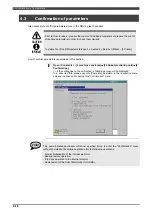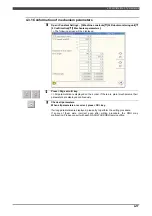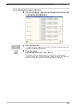
4.2 Setting of parameters
4-11
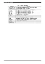
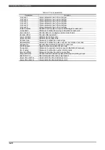
Table 4-6 Signal parameters
Parameter
Function
Default
value
Tool number watch
Enable / Disable the Tool number watch function.
Disabled
Teach protect stop
Enable / Disable the protective stop function in the Teach mode.
Disabled
H-teach (safety plug)
Enable / Disable the safety plug condition in the High-speed teach mode.
Enabled
Logic condition
Enable / Disable the MOTORS ON condition of the logical operation function.
Enabled
Tool number watch sig.
This is to set the input signal number of Tool number watch signal.
101
Stop watch signal
This is to set the input signal number of Stopping watch signal.
0
Robot select sig.
This is to set the input signal number of Robot selection signal.
0
TCP Speed watch signal 1 – 4
This is to set the input signal number of TCP speed monitoring in playback.
0
AXES speed watch signal 1 -4
This is to set the input signal number of AXES speed monitoring in playback.
0
Zone limit sig. 1 – 4
This is to set the input signal number of Zone limit signal in playback.
0
Tool posture watch sig. 1 - 4
This is to set the input signal number of Tool posture watch sig.
0
Tool number input sig. 1 - 5
This is to set the input signal number of Tool number input signal.
1,2,3,4,5
Network logic condition
Enabled
Network Emg.Stop sig.
0
Network safety plug sig.
0
Network Prot. stop sig.
0
Network Ext.enable sig.
0
Network remote sig.
0
Network Ext.teach sig.
0
Network Ext.playback sig.
0
Network Ext.H-teach sig.
These items are displayed in case of RMU20-30 or RMU20-40.
See "5.2.2 Assignment of the network I/O signals".
0
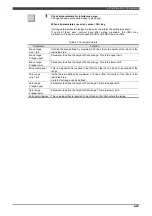
(Supplement)
- To change the parameter of "Tool number watch",
EXPERT
or higher operator class is necessary.
For the other parameters,
SPECIALIST
is necessary
- For the signals, "General safety input" (1-5) or "Safety network input signals" (101-164) can be used.
The "Safety network input signals" are available only in case of the RMU20-30 or the RMU20-40.
Summary of Contents for RMU20-20
Page 2: ......
Page 6: ...Contents 4 ...
Page 8: ......
Page 26: ...1 4 EC DECLARATION OF CONFORMITY FOR MACHINERY 1 18 NOTE ...
Page 68: ...2 9 Enabling RMU 2 40 NOTE ...
Page 70: ......
Page 100: ...3 4 Setting when a slider unit is used 3 30 NOTE ...
Page 102: ......
Page 138: ...4 4Approval 4 36 8 Approval is completed The following screen will be displayed ...
Page 144: ......
Page 154: ...5 4Trouble shooting 5 10 NOTE ...
Page 156: ......
Page 166: ...6 4Trouble shooting 6 10 NOTE ...
Page 168: ......
Page 189: ......


