3.2Operation procedure
3-9
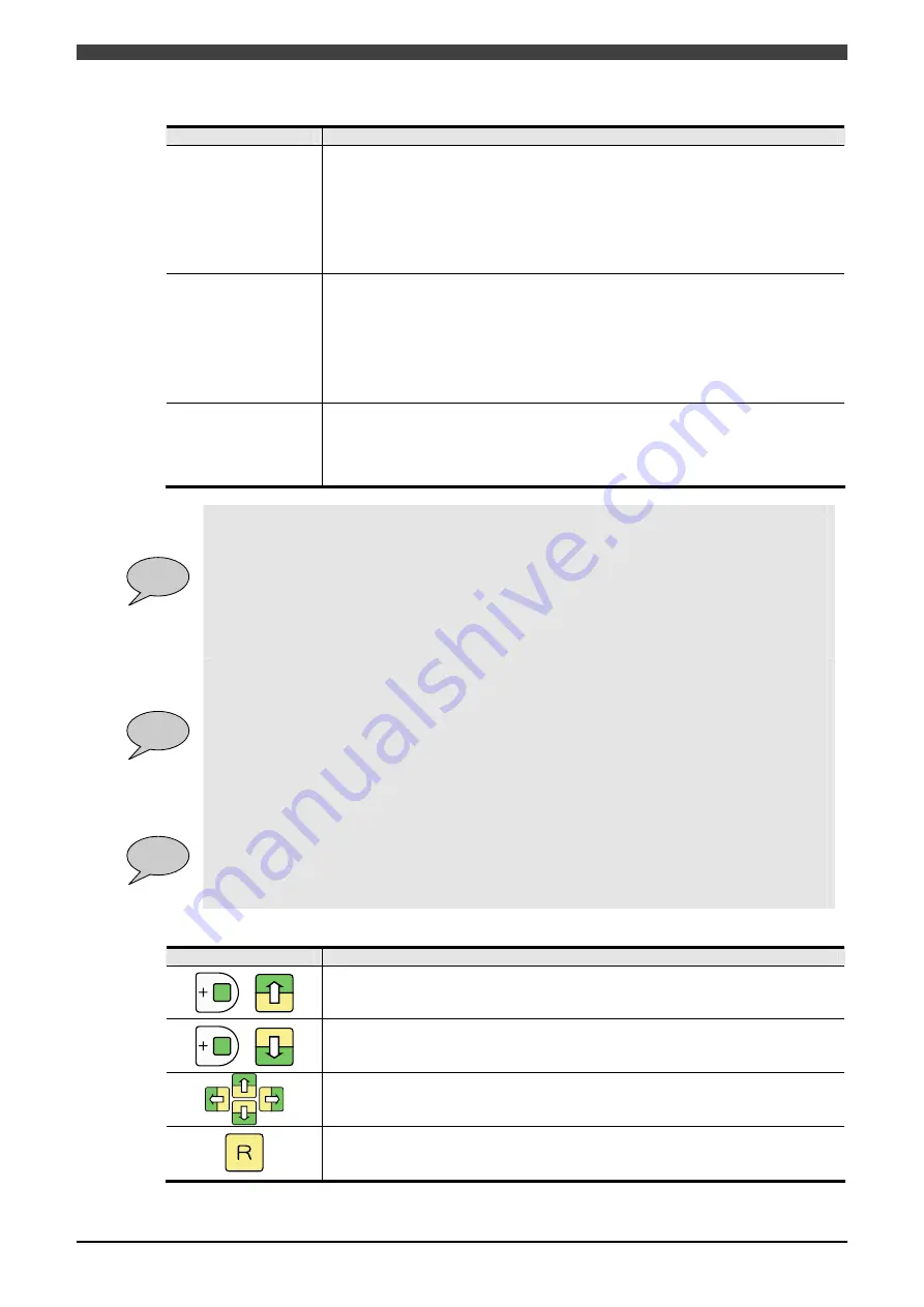
Table 3.2.3 Items to be set on Range Setting Screen
Parameter
Function
Fence Range
This range covers outside of a maximum of eight lines, which are defined from the
center of the robot at random, as the limit area. It also enables specification of limit
area in the Z direction.
Origin offset : Offset value of the origin coordinates.
Exit permission signal : This is a signal that is required to be ON when the robot is
trying to go outside of the range
(General safety input 1-5 or Safety network input 101-164 can be assigned)
(NOTE)The safety network input signals are available only in case of RMU20-30.
Part Range
This range covers inside of a maximum of three parts, which are defined from the
center of the robot at random, as the limit area. The parts are defined by a
maximum of four lines. The range also enables specification of limit area in the Z
direction.
Entry permission signal : This is a signal that is required to be ON when the robot
enters the range
(General safety input 1-5 or Safety network input 101-164 can be assigned)
(NOTE)The safety network input signals are available only in case of RMU20-30.
Graphic Display
The graphic display makes it possible to confirm limit areas with range settings
made as well as settings of sphere / form / arm limits.
The graphic display enables switching of screens Top
Side
Rear.
By executing manual operation while the graphic display is in operation, the
positions of the sphere / form / arm limits are updated in real time.
POINT
Fence Range:
Used to specify lines to be regulated by entering X-Y coordinate values at two points.
If the values of X1, X2, Y1, Y2 are all “0.0”, no regulations will be executed by the line concerned.
Furthermore, if the upper and lower limits in the Z direction are both “0.0”, no regulations will be
executed in the Z direction.
If the two coordinates at two points entered are the same, if a distance from the line found by
coordinates at two points and the home position is not more than 50 mm, or if a value larger than
the upper limit value is set to the lower limit value in the Z direction, pressing any valid f key will
alert operator to an error through displaying it on the pop-up window.
POINT
Part Range:
Used to specify a angle formed with three limit lines or a box formed with four limit lines as limit
area.
If the upper and lower limits in the Z direction are both “0.0”, no regulations will be executed in the
Z direction.
If the two coordinates at two points entered are the same, if coordinate values not forming a
triangle or a box are specified, or if a value larger than the upper limit value is set to the lower limit
value in the Z direction, pressing any valid f key will alert operator to an error through displaying it
on the pop-up window.
POINT
Graphic Display:
The length of a side is calculated from individual movement ranges of the robot.
The movement limit areas are displayed in red, and the sphere, form, and arm that become limit
objects are displayed by color code. If the robot goes into or is about to go into a movement limit
area with the sphere, form, and arm that become limit objects as well as rear coordinate value
displayed in red, an error will occur.
Table 3.2.4 Cursor Control on Graphic Display Screen
Key
Function
+
Used to increase the magnification of the graphic display.
The display can be enlarged up to 15
at maximum.
+
Used to reduce the magnification of the graphic display.
Used to move the center position of drawing in each direction.
Used to close the Graphic Display screen and return to the “Range Setting” screen.
Summary of Contents for RMU20-20
Page 2: ......
Page 6: ...Contents 4 ...
Page 8: ......
Page 26: ...1 4 EC DECLARATION OF CONFORMITY FOR MACHINERY 1 18 NOTE ...
Page 68: ...2 9 Enabling RMU 2 40 NOTE ...
Page 70: ......
Page 100: ...3 4 Setting when a slider unit is used 3 30 NOTE ...
Page 102: ......
Page 138: ...4 4Approval 4 36 8 Approval is completed The following screen will be displayed ...
Page 144: ......
Page 154: ...5 4Trouble shooting 5 10 NOTE ...
Page 156: ......
Page 166: ...6 4Trouble shooting 6 10 NOTE ...
Page 168: ......
Page 189: ......


