2.7 Logical operation output function
2-37
2.8 RMU error signal output (Application signals)
The errors of the RMU can be assigned to the output signals of application signals. By assigning those signals,
it is possible to detect the condition of the RMU from the external devices e.g. PLC etc. When shipping, those
signals are not assigned. If necessary, please make an assignment setting referring to this section.
RMU errors that can be outputted
(For details, refer to “6.2 Trouble shooting”)
No.
Error message
1100 RMU
Encoder
failure
1101
RMU Joint angle exceeded
1102
RMU Pos. exceeded limit area
1103
RMU Speed failure
1104
RMU Over current
1105 RMU
Disparity
failure
1106
RMU Internal failure
1107
RMU Not approved
1108
RMU Communication stop
1109
RMU Stop monitor failure
1110
RMU Pos. monitor failure
1111
RMU Pos. disparity failure
1112
RMU Vel. Disparity failure
1113
RMU Connection failure
1114
RMU Tool monitor failure
Assignment for the output signals
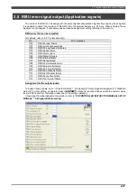
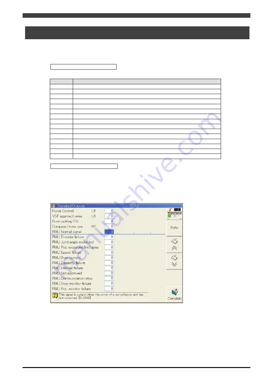
To assign those signals, open “<Constant Setting> - [6 Signals] [3 Output Signal Assignment] [1 Standard
Outputs]”. For this setting, an operator class of
EXPERT
or higher is required (Please switch the operator class
level via R314 shortcut command in advance of this setting operation).
Concerning the signal assignment operations, refer to
“FD CONTROLLER INSTRUCTION MANUAL SETUP
MANUAL” “4.6 Signal attribute setting“
.
Summary of Contents for RMU20-20
Page 2: ......
Page 6: ...Contents 4 ...
Page 8: ......
Page 26: ...1 4 EC DECLARATION OF CONFORMITY FOR MACHINERY 1 18 NOTE ...
Page 68: ...2 9 Enabling RMU 2 40 NOTE ...
Page 70: ......
Page 100: ...3 4 Setting when a slider unit is used 3 30 NOTE ...
Page 102: ......
Page 138: ...4 4Approval 4 36 8 Approval is completed The following screen will be displayed ...
Page 144: ......
Page 154: ...5 4Trouble shooting 5 10 NOTE ...
Page 156: ......
Page 166: ...6 4Trouble shooting 6 10 NOTE ...
Page 168: ......
Page 189: ......


