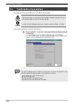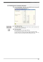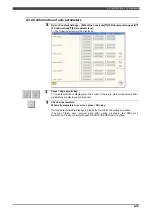
4.3Confirmation of parameters
4-20
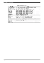
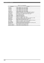
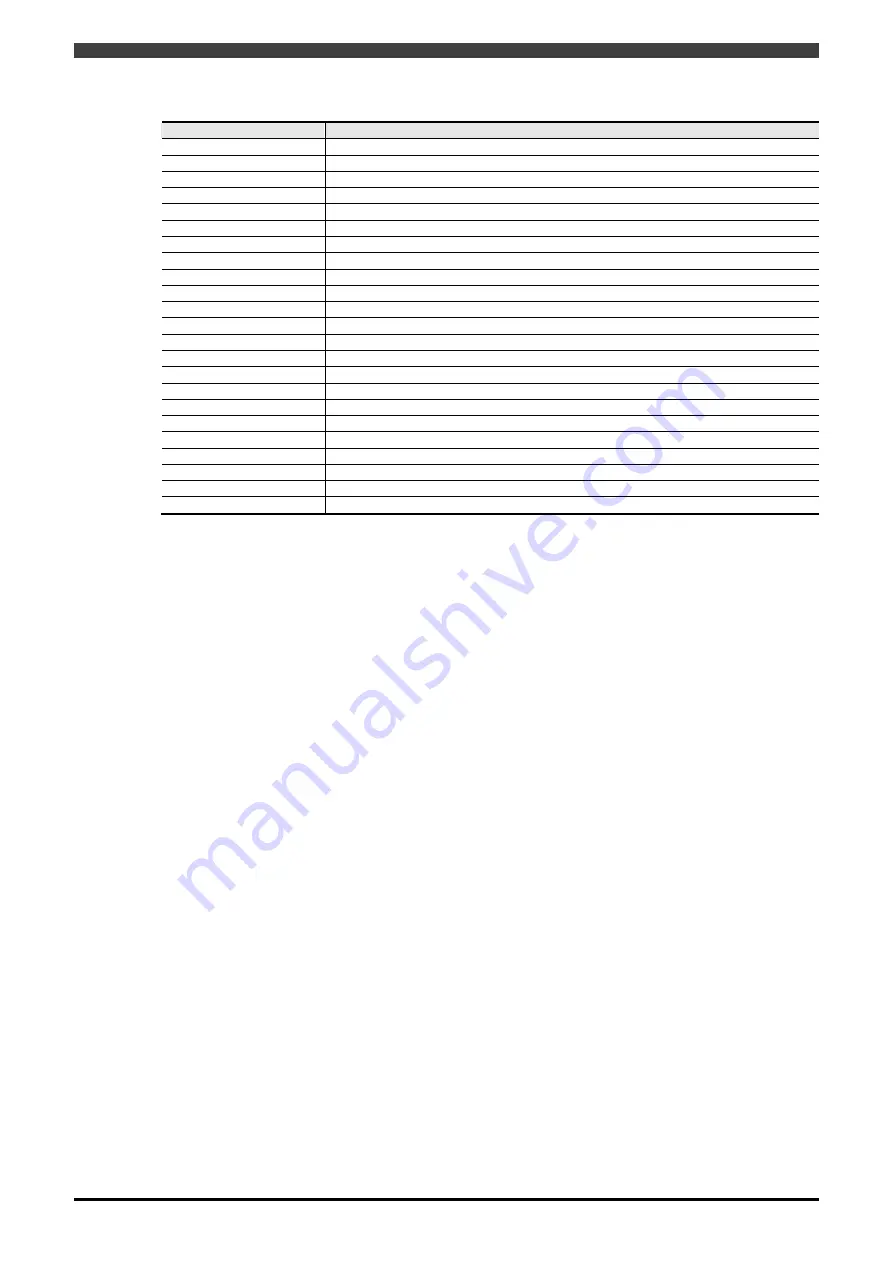
Table 4-11 Axes parameters
Parameter
Function
Link coef. 1
Unique parameter due to the robot type
Link coef. 2
Unique parameter due to the robot type
Link coef. 3
Unique parameter due to the robot type
Link coef. 4
Unique parameter due to the robot type
Link coef. 5
Unique parameter due to the robot type
Link coef. 6
Unique parameter due to the robot type
Pulse constant
Needed encoder pulse to move specified angle for each joint
Joint pattern
Parameter to define the moving construction for each joint
Axis constant
Encoder data of zero degree position for each axis
Encoder offset
Encoder offset parameter
Lower soft limit
Software limit of lower side
Upper soft limit
Software limit of upper side
Encoder type
Parameter to define the encoder type
Radians/pulse
Parameter to define the pulse count per one rotation of encoder
Std.pos.Enc
Encoder data of reference position for each axis
Std.Pos.Angle
Angle of reference position for each axis
Connection
Parameter to connect or not to connect to the RMU (0=connect)
No. of poles
Parameter to define the number of motor poles
Elec.Ang.Offset
Parameter to define the electric angle offset
Stop watch limit
Position abnormal deviation (pulse) when stop monitoring is input
Speed limit 1-4
Abnormal speed ratio (rpm) in high speed
Upper Zone limit 1-4
Upper limit of the Zone limit (deg or mm)
Lower Zone limit 1-4
Lower limit of the Zone limit (deg or mm)
Summary of Contents for RMU20-20
Page 2: ......
Page 6: ...Contents 4 ...
Page 8: ......
Page 26: ...1 4 EC DECLARATION OF CONFORMITY FOR MACHINERY 1 18 NOTE ...
Page 68: ...2 9 Enabling RMU 2 40 NOTE ...
Page 70: ......
Page 100: ...3 4 Setting when a slider unit is used 3 30 NOTE ...
Page 102: ......
Page 138: ...4 4Approval 4 36 8 Approval is completed The following screen will be displayed ...
Page 144: ......
Page 154: ...5 4Trouble shooting 5 10 NOTE ...
Page 156: ......
Page 166: ...6 4Trouble shooting 6 10 NOTE ...
Page 168: ......
Page 189: ......


