2.2 Description of Exterior and Parts
2-13
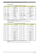
12) CN4 (RMU20-30, RMU20-40)
Table 2-12 Connector CN4
Pin no.
Circuit code
I/O
Signal name
Pin no.
Circuit code
I/O
Signal name
(A1) IN9A+
SI
General input 11+
(Note)
(B1) IN9A-
SI
General input 11-
(Note)
(A2) IN9B+
SI
General input 12+
(Note)
(B2) IN9B-
SI
General input 12-
(Note)
(A3) IN10A+
SI
General input 21+
(Note)
(B3) IN10A-
SI
General input 21-
(Note)
(A4) IN10B+
SI
General input 22+
(Note)
(B4) IN10B-
SI
General input 22-
(Note)
(A5) IN11A+
SI
General input 31+
(Note)
(B5) IN11A-
SI
General input 31-
(Note)
(A6) IN11B+
SI
General input 32+
(Note)
(B6) IN11B-
SI
General input 32-
(Note)
(A7) IN12A+
SI
General input 41+
(Note)
(B7) IN12A-
SI
General input 41-
(Note)
(A8) IN12B+
IS
General input 42+
(Note)
(B8) IN12B-
SI
General input 42-
(Note)
(A9) IN13A+
SI
General input 51+
(Note)
(B9) IN13A-
SI
General input 51-
(Note)
(A10) IN13B+
SI
General input 52+
(Note)
(B10) IN13B-
SI
General input 52-
(Note)
Receptacle housing at cable side: JST Mfg. No. J21DF-20V-KY, 20 contacts, Y-type
SI: safety input
(Note)
Used for area select signal, stop monitoring signal or playback speed monitoring select signal.
13) CNEIP (RMU20-30)
This is a RJ45 connector for the Ethernet communication.
Summary of Contents for RMU20-20
Page 2: ......
Page 6: ...Contents 4 ...
Page 8: ......
Page 26: ...1 4 EC DECLARATION OF CONFORMITY FOR MACHINERY 1 18 NOTE ...
Page 68: ...2 9 Enabling RMU 2 40 NOTE ...
Page 70: ......
Page 100: ...3 4 Setting when a slider unit is used 3 30 NOTE ...
Page 102: ......
Page 138: ...4 4Approval 4 36 8 Approval is completed The following screen will be displayed ...
Page 144: ......
Page 154: ...5 4Trouble shooting 5 10 NOTE ...
Page 156: ......
Page 166: ...6 4Trouble shooting 6 10 NOTE ...
Page 168: ......
Page 189: ......


