5.2Setting for RMU
5-2
5.2
Setting for RMU
5.2.1
Safety network parameter
The RMU communication parameters are to be set using the teach pendant.
It is not possible to make the setting using a safety network setting utilities like RSLogix5000 etc.
The Safety network parameters can be set in the menu of <Constant settings> - [3 Machine constant] [34
Robot Monitoring Unit] [1 Settings] [9 Safety network parameters].
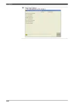
To set the Safety network parameters, open the menu of <Constant setting> - [3 Machine constant] [34 Robot
Monitoring Unit] [1 Settings] [9 Safety network parameters].
For details, refer to "4.2.6 Setting the Safety network parameters".
5.2.2
Assignment of the network I/O signals
In the I/O signal assignment screen, it is possible to assign the functions to the network signals.
The "Signal parameters" can be set in the menu of <Constant settings> - [3 Machine constant] [34 Robot
Monitoring Unit] [1 Settings] [7 Signal parameters].
(For details, refer to "4.2.4 Setting of signal parameters".)
In this section, the specific functions that use the network signals are explained.
Those functions can be assigned to the network signals in the following screen.
Network logic condition
This is a software switch to decide if the "
Motors ON condition
" is included to the logical operation of the safety
network output signal or not. When "Enabled", the safety network output signal turns OFF if the "
Motors ON
condition
" is OFF.
Network emergency stop signal
If this signal is assigned, the emergency stop condition will be made while the assigned signal is OFF.
Therefore, to release the emergency stop of the robot controller, it is necessary to satisfy the all of the
following conditions.
1. The emergency stop button on the robot controller is released.
2. The emergency stop button on the teach pendant is released.
3. The external emergency stop signal is released. (or the terminals are jumpered)
4. The network emergency stop signal is ON.
If "0" is set, this function is disabled.
Summary of Contents for RMU20-20
Page 2: ......
Page 6: ...Contents 4 ...
Page 8: ......
Page 26: ...1 4 EC DECLARATION OF CONFORMITY FOR MACHINERY 1 18 NOTE ...
Page 68: ...2 9 Enabling RMU 2 40 NOTE ...
Page 70: ......
Page 100: ...3 4 Setting when a slider unit is used 3 30 NOTE ...
Page 102: ......
Page 138: ...4 4Approval 4 36 8 Approval is completed The following screen will be displayed ...
Page 144: ......
Page 154: ...5 4Trouble shooting 5 10 NOTE ...
Page 156: ......
Page 166: ...6 4Trouble shooting 6 10 NOTE ...
Page 168: ......
Page 189: ......


