130
Rev 2.10 • 17 Feb 11
6. Control Panels
FECP
The FECP has a complete audio monitor/meter control section. It has 12 function buttons in 3 rows.
The 12 buttons are independently configurable (despite the labeling on the panel). Each button
directs an audio to the meters, to m monitor A, or monitor B. There are 5 audio sources: program
audio, preset audio, preview audio, audio from “Aux In” or audio from the “off-air” channel.
Each monitor includes a gain control knob and a ‘dim” button. (Monitor/meter functions can also
be found in the audio menus.)
The FECP has 2 program audio knobs. (One adjusts the program level and the other adjusts the
over-to-main ratio.)
The FECP has 3 system control buttons and 12 transition control buttons. These buttons are config-
urable.
The surface of the FECP is light gray and dark gray.
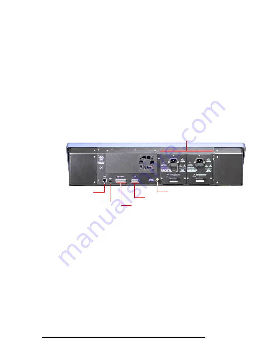
At the rear of the panel are 2 power connections, an Ethernet port, a USB port, a ‘CP Aux’ connec-
tor (DB15) used for the optional TLA, and a GPI/alarm connector (DB25), and an audio metering
input.
Figure 6 -11. FECP (rear)
FECP Buttons
Panel buttons are large and appear in several colors (green, amber, red, blue, white, and violet) and
3 brightness levels: off, low-tally, and high-tally. They are dynamically re-legendable, displaying 3
lines of text, 8 characters per line. (The text might be blank.)
High-tally red and high-tally amber usually indicate errors or warnings.
S
Buttons for sources that are selected on the program bus can be configured to appear in one of 3
ways: high-tally green (normal), high-tally white, or high-tally red. In the last case, red does not
necessarily represent an error condition. The button legend, however,
does
indicate whether the
source is good or bad.
The buttons allow you to select channels, choose sources, options, video effects, and audio overs,
and perform other functions. Some buttons can serve as status buttons.
Pressing a deselected toggle button will cause it to become selected. Pressing a selected toggle but-
ton will make it deselected.
Audio Metering Input
Ethernet
Connector
Power Connectors
TLA Connector
USB port
GP I/Alarms Connectors
Summary of Contents for NV5100MC Master Control
Page 14: ...xiv Rev 2 10 17 Feb 11 Table of Contents ...
Page 54: ...40 Rev 2 10 17 Feb 11 3 Frames Other Modules ...
Page 92: ...78 Rev 2 10 17 Feb 11 4 MCPMs Other General Features ...
Page 112: ...98 Rev 2 10 17 Feb 11 5 MCEs Summary ...
Page 158: ...144 Rev 2 10 17 Feb 11 6 Control Panels Aux Preview GUI ...
Page 166: ...152 Rev 2 10 17 Feb 11 7 Other MC Products Device Controller ...
Page 224: ...210 Rev 2 10 17 Feb 11 C Misc Information NorthAmerican andInternational PowerCords ...
Page 240: ...226 Rev 2 10 17 Feb 11 Index ...


