56
7. Once the cleaner stops flowing from the door spout,
close the draw valve and press the Wash symbol
,
canceling the Wash mode.
Note:
The shake draw valve will automatically close
when the Wash operation is canceled.
8. Pour 2 gal. (7.6 L) of cool, clean water into the shake
mix hopper and
repeat steps 3 through 7
.
9. Prepare 2.5 gal. (9.5 L) of KAY-5
®
Sanitizer (HCS)
solution. Use one packet in 2.5 gal. (9.5 L) of water
(100 ppm).
10. Pour the sanitizing solution into the hopper and
repeat steps 4 through 7
.
11.
Repeat steps 1 through 10
for the soft serve side of
the freezer.
Disassembly—Shake Side
Note:
Failure to remove the parts specified below for
brush-cleaning and lubrication will damage the machine.
These parts must be removed every 14 days or the
machine will lock out and will not operate.
1. Make sure the power switch is in the OFF position.
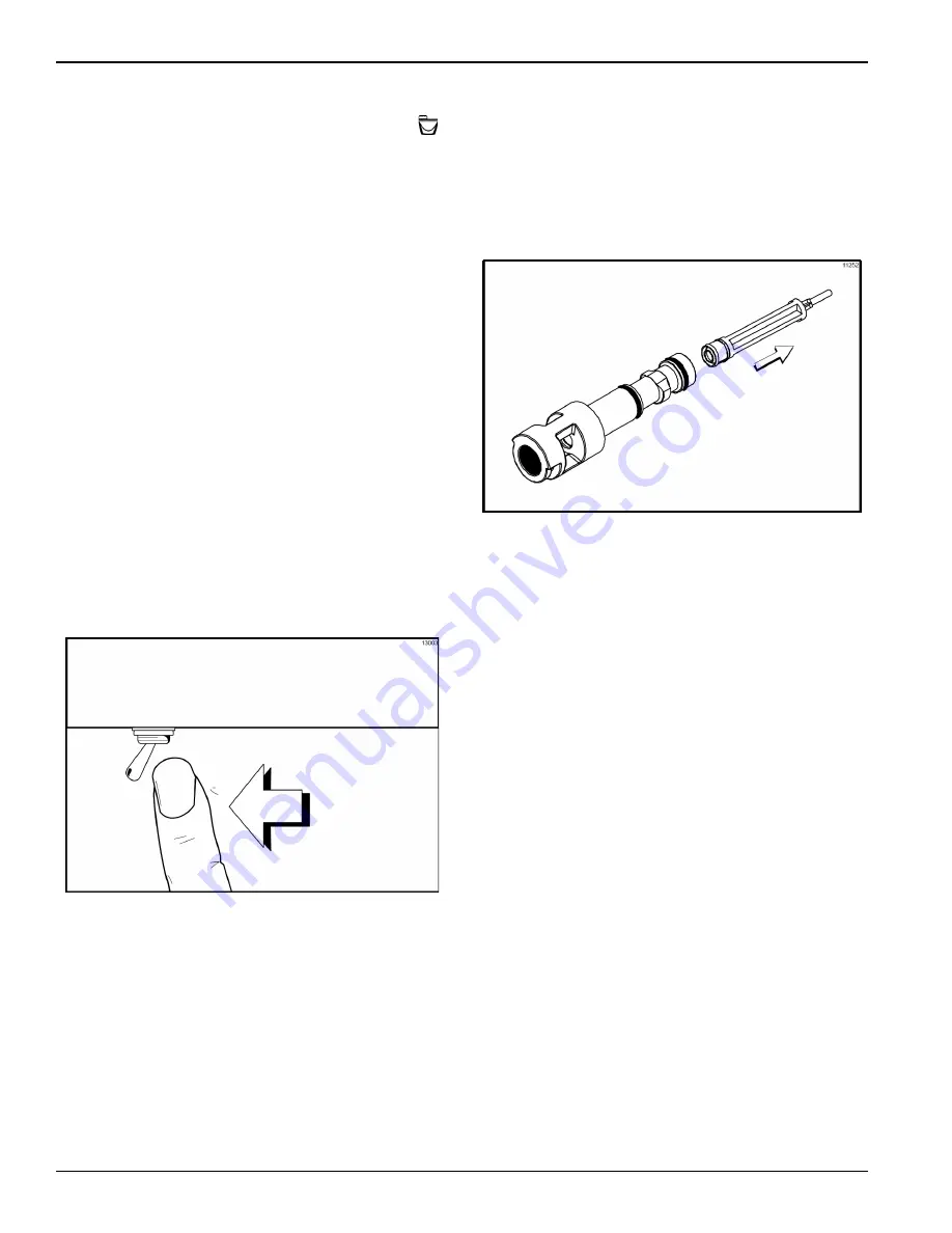
Figure-101
2. Remove the hole plugs from the syrup ports, and
remove the restrictor cap from the bottom of the door
spout.
3. Remove the spinner blade from the bottom of the
door spout by lifting up the locking collar on the
spinner coupling and pulling down the blade.
4. Remove the handscrews, freezer door, beater
assembly, driveshaft, driveshaft seal, and scraper
blades from the freezing cylinder.
5. Remove the driveshaft seal from the driveshaft.
6. Remove the freezer door O-ring, front bearing,
retainer pins, and the draw valve spinner assembly.
7. Remove the driven spinner from the draw valve by
grasping the draw valve and pulling the driven
spinner out. Remove the spinner shaft seal.
Figure-102
8. Remove the two O-rings from the draw valve.
Note:
To remove O-rings, use a clean, sanitized towel to
grasp the O-ring. Apply pressure in an upward direction
until the O-ring pops out of its groove. With the other
hand, push the top of the O-ring forward; it will roll out of
the groove and can easily be removed. If there is more
than one O-ring to be removed, always remove the rear
O-ring first. This will allow the O-ring to slide over the
forward O-rings without falling into the open grooves.
9. From the shake pump cylinder, remove the retaining
pin, mix inlet adaptor, valve cap, pump gasket, and
piston. Remove the O-ring from the piston and valve
cap.
Summary of Contents for C602
Page 2: ......
Page 9: ...7 Front View Figure 2 1 2 3 4 5 7 7a 10 11 8 8 9 7c 7b 6 12 13 14 ...
Page 21: ...19 Beater Door Assembly Shake Side Figure 11 6 4 1 3 2 5 17 11 13 12 7 8 10 9 14 15 16 ...
Page 23: ...21 Beater Door Assembly Soft Serve Side Figure 12 2 3 11 4 5 12 13 1 14 15 16 6 8 7 6 9 10 ...
Page 25: ...23 X53800 BRN TAN Syrup Pump Figure 13 3 4 2g 5 1 2e 2f 2d 2c 2a 2b 2 2h ...
Page 114: ...057888 M ...


