


Chapter 15. XG-SIM
15-21
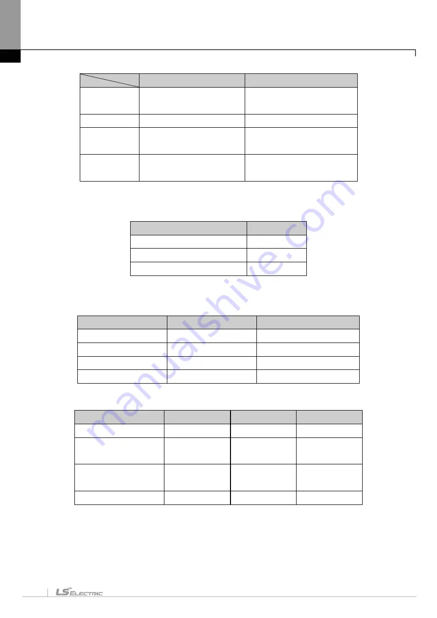
Not setting I/O module
Setting I/O module
Change Input
Use the monitor’s current
value change
Use the XG-SIM channel value
change
Change output
Unable to change
Unable to change
Forcible I/O
input
Not applicable
Input forcibly set input
Forcible I/O
output
Not applicable
Output forcibly set output
3) Analog Input Module (A/D conversion module)
For the analog input module supported by XG-SIM, refer to the following table.
Module name
Support
XGF-AV8A (Voltage type 8ch)
○
XGF-AC8A (Current type 8ch)
○
XGF-AD4S (Insulation type 4ch)
Ⅹ
XG-SIM supports 4 types of input voltage ranges and digital data formats and 2 kinds of input current ranges
as follows.
Input voltage range
Input current range
Digital output format
1 ~ 5V
4 ~ 20mA
0 ~ 16000
0 ~ 5V
0 ~ 20mA
-8000 ~ 8000
0 ~ 10V
-
1000 ~ 5000
-10 ~ 10V
-
0 ~ 10000 (%)
XG-SIM supports the following analog input parameters.
Parameter
Support
Parameter
Support
Operation channel
○
Filter constant
○
Input voltage(current)
range
○
Averaging
○
Output data type
○
Averaging
method
○
Filter process
Ⅹ
Average
○
Analog input may be directly set in XG-SIM window and the input range is valid only within the input voltage
(current) range set in the parameter.
Summary of Contents for XGT Series
Page 7: ...Safety Instruction 6 ...
Page 11: ...About User s Manual 2 ...
Page 34: ...Chapter 1 Introduction 1 9 11 Wait a second for the installation to be complete ...
Page 47: ...Chapter 1 Introduction 1 22 ...
Page 69: ...Chapter 2 Basic Application 2 22 ...
Page 74: ...Chapter 2 Basic Application 2 27 ...
Page 91: ...Chapter 2 Basic Application 2 44 ...
Page 118: ...Chapter 3 Project 3 27 Dialog Box a b c d f e h g ...
Page 154: ...Chapter 3 Project 3 63 ...
Page 156: ...Chapter 3 Project 3 65 3 Specify the communication module in the I O parameters ...
Page 171: ...Chapter 3 Project 3 80 ...
Page 174: ...Chapter 4 Variable Comment 4 3 4 1 3 View flag Dialog Box Description of Dialog Box a b c d ...
Page 192: ...Chapter 4 Variable Comment 4 21 ...
Page 197: ...Chapter 4 Variable Comment 4 26 ...
Page 203: ...Chapter 4 Variable Comment 4 32 5 Save the EtherNet IP variable as CSV file ...
Page 218: ...Chapter 4 Variable Comment 4 47 Dialog box ...
Page 219: ...Chapter 4 Variable Comment 4 48 ...
Page 221: ...Chapter 4 Variable Comment 4 50 ...
Page 269: ...Chapter 5 LD Edit 5 48 ...
Page 297: ...Chapter 6 IL Edit 6 28 3 Click Go To ...
Page 331: ...Chapter 8 Find Replace 8 4 Note Advanced Button is pressed ...
Page 344: ...Chapter 8 Find Replace 8 17 ...
Page 354: ...Chapter 8 Find Replace 8 27 ...
Page 363: ...Chapter 8 Find Replace 8 36 ...
Page 365: ...Chapter 8 Find Replace 8 38 ...
Page 455: ...Chapter 10 Online 10 60 4 If you press OK the changed items are displayed ...
Page 482: ...Chapter 10 Online 10 87 ...
Page 487: ...Chapter 10 Online 10 92 ...
Page 603: ...Chapter 11 Communication and Special Function Blocks 11 116 ...
Page 625: ...Chapter 13 Online Editing 13 4 ...
Page 635: ...Chapter 14 Print 14 10 ...
Page 690: ...Chapter 16 SFC Edit 16 25 3 Move cursor to the area to paste to 4 Select menu Edit Paste ...
Page 715: ...Chapter 17 ST Edit 17 8 Dialog ...
Page 731: ...Chapter 17 ST Edit 17 24 ...
Page 763: ...Chapter 18 Exclusive Functions for Event Input Module 18 32 ...
Page 766: ...Chapter 19 User Function Function Block 19 3 h g a b c d e f Dialog box ...
Page 773: ...Chapter 19 User Function Function Block 19 10 ...
Page 783: ...Chapter 19 User Function Function Block 19 20 ...
Page 801: ...Chapter 20 LS Studio 20 18 7 After setting the save area select the OK button ...
Page 803: ...Warranty and Environment Policy 2 ...