


Chapter 11. Communication and Special Function Blocks
11-76
-
The ‘Max. samples to display’ can not be greater than the ‘Max. sample to keep’.
-
The ‘Max. time to display’ can not be greater than the ‘Max. time to keep’.
-
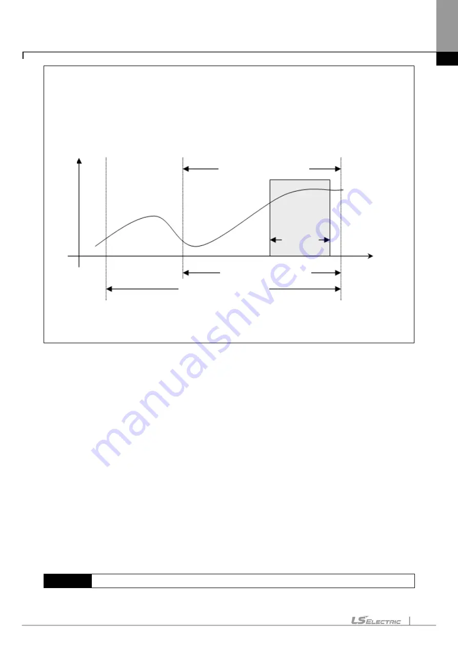
The relationship between the Max. samples to keep and the Max. sample to displayed is as shown
below. In the figure below, ‘Graph’ is of a graph area presently displayed on the screen, which is
available to scroll horizontally as many as the max. samples displayed.
-
The Max. samples to keep means the max. number of samples available to save on the file.
Refer to the section of 11.7.5 ‘8) Text’.
e. Frequency: used to specify the cycle to read data from PLC. The shorter the cycle is, the more correct the
data is, which may have an influence on PLC scan and PC performance, though.
f. Device Setting: used to designate the device to monitor. The device can be displayed in bit or in real as
specified.
g. OK: applies the changed items and closes the dialog box.
h. Cancel: closes the dialog box.
1) Setting Bit Device
It is used to input the bit device to monitor.
[Sequence]
1. Select the bit graph tap on the Setting Monitoring dialog box.
2. Input the device of bit type. Or double-click the variable column to select the declared device on the
Variable/Comment dialog box.
Notes
Value
Max. sample to display
Graph
Time
Max. sample to keep
Scroll available section
Summary of Contents for XGT Series
Page 7: ...Safety Instruction 6 ...
Page 11: ...About User s Manual 2 ...
Page 34: ...Chapter 1 Introduction 1 9 11 Wait a second for the installation to be complete ...
Page 47: ...Chapter 1 Introduction 1 22 ...
Page 69: ...Chapter 2 Basic Application 2 22 ...
Page 74: ...Chapter 2 Basic Application 2 27 ...
Page 91: ...Chapter 2 Basic Application 2 44 ...
Page 118: ...Chapter 3 Project 3 27 Dialog Box a b c d f e h g ...
Page 154: ...Chapter 3 Project 3 63 ...
Page 156: ...Chapter 3 Project 3 65 3 Specify the communication module in the I O parameters ...
Page 171: ...Chapter 3 Project 3 80 ...
Page 174: ...Chapter 4 Variable Comment 4 3 4 1 3 View flag Dialog Box Description of Dialog Box a b c d ...
Page 192: ...Chapter 4 Variable Comment 4 21 ...
Page 197: ...Chapter 4 Variable Comment 4 26 ...
Page 203: ...Chapter 4 Variable Comment 4 32 5 Save the EtherNet IP variable as CSV file ...
Page 218: ...Chapter 4 Variable Comment 4 47 Dialog box ...
Page 219: ...Chapter 4 Variable Comment 4 48 ...
Page 221: ...Chapter 4 Variable Comment 4 50 ...
Page 269: ...Chapter 5 LD Edit 5 48 ...
Page 297: ...Chapter 6 IL Edit 6 28 3 Click Go To ...
Page 331: ...Chapter 8 Find Replace 8 4 Note Advanced Button is pressed ...
Page 344: ...Chapter 8 Find Replace 8 17 ...
Page 354: ...Chapter 8 Find Replace 8 27 ...
Page 363: ...Chapter 8 Find Replace 8 36 ...
Page 365: ...Chapter 8 Find Replace 8 38 ...
Page 455: ...Chapter 10 Online 10 60 4 If you press OK the changed items are displayed ...
Page 482: ...Chapter 10 Online 10 87 ...
Page 487: ...Chapter 10 Online 10 92 ...
Page 603: ...Chapter 11 Communication and Special Function Blocks 11 116 ...
Page 625: ...Chapter 13 Online Editing 13 4 ...
Page 635: ...Chapter 14 Print 14 10 ...
Page 690: ...Chapter 16 SFC Edit 16 25 3 Move cursor to the area to paste to 4 Select menu Edit Paste ...
Page 715: ...Chapter 17 ST Edit 17 8 Dialog ...
Page 731: ...Chapter 17 ST Edit 17 24 ...
Page 763: ...Chapter 18 Exclusive Functions for Event Input Module 18 32 ...
Page 766: ...Chapter 19 User Function Function Block 19 3 h g a b c d e f Dialog box ...
Page 773: ...Chapter 19 User Function Function Block 19 10 ...
Page 783: ...Chapter 19 User Function Function Block 19 20 ...
Page 801: ...Chapter 20 LS Studio 20 18 7 After setting the save area select the OK button ...
Page 803: ...Warranty and Environment Policy 2 ...