


Chapter 9. Parameters
9-3
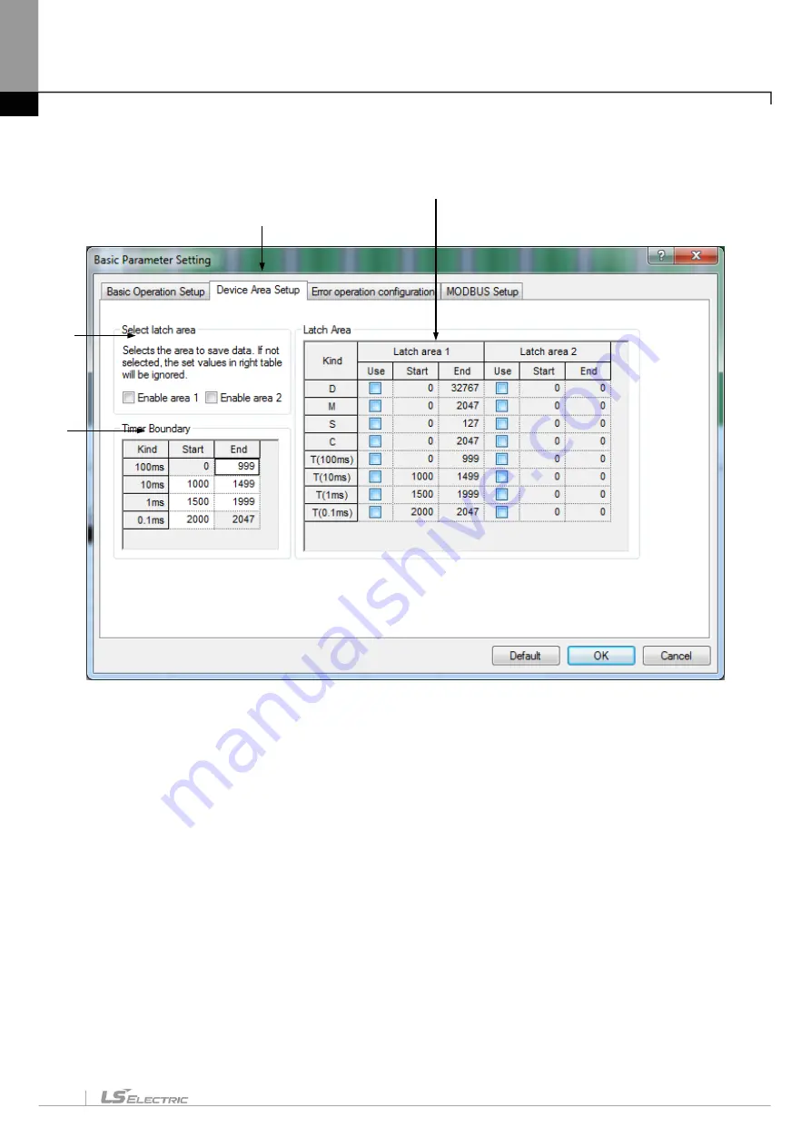
2. Device Area Setup
[Dialog Box]
[Description of Dialog Box]
a. Device Area Setup: used to specify the area to preserve (latch area) of [Basic Parameters] information
even when PLC power is off.
b. Select latch area: used to specify data area to preserve. It is the representative flag to control area 1 and
area 2 of the right latch area table. If the check box is not selected, value specified in the right latch area
table will be ignored.
c. It is used to specify desired latch area for each device, to decide to use the respective device and to
select the area. Area 1 and area 2 can not be used as overlapped, and the maximum size of each latch
area is the maximum size of the device area.
d. Timer areas are divided into 100ms, 10ms, 1ms and 0.1ms. This area can be selected as the latch area
within the specified value of the left timer limit area. Like other devices the areas can not be set as
overwritten. The number of timers to use can be adjusted, and the value specified here will have a great
influence on the timer of LD diagram or IL program. Default for setting value of each timer is as follows;
a
b
c
d
Summary of Contents for XGT Series
Page 7: ...Safety Instruction 6 ...
Page 11: ...About User s Manual 2 ...
Page 34: ...Chapter 1 Introduction 1 9 11 Wait a second for the installation to be complete ...
Page 47: ...Chapter 1 Introduction 1 22 ...
Page 69: ...Chapter 2 Basic Application 2 22 ...
Page 74: ...Chapter 2 Basic Application 2 27 ...
Page 91: ...Chapter 2 Basic Application 2 44 ...
Page 118: ...Chapter 3 Project 3 27 Dialog Box a b c d f e h g ...
Page 154: ...Chapter 3 Project 3 63 ...
Page 156: ...Chapter 3 Project 3 65 3 Specify the communication module in the I O parameters ...
Page 171: ...Chapter 3 Project 3 80 ...
Page 174: ...Chapter 4 Variable Comment 4 3 4 1 3 View flag Dialog Box Description of Dialog Box a b c d ...
Page 192: ...Chapter 4 Variable Comment 4 21 ...
Page 197: ...Chapter 4 Variable Comment 4 26 ...
Page 203: ...Chapter 4 Variable Comment 4 32 5 Save the EtherNet IP variable as CSV file ...
Page 218: ...Chapter 4 Variable Comment 4 47 Dialog box ...
Page 219: ...Chapter 4 Variable Comment 4 48 ...
Page 221: ...Chapter 4 Variable Comment 4 50 ...
Page 269: ...Chapter 5 LD Edit 5 48 ...
Page 297: ...Chapter 6 IL Edit 6 28 3 Click Go To ...
Page 331: ...Chapter 8 Find Replace 8 4 Note Advanced Button is pressed ...
Page 344: ...Chapter 8 Find Replace 8 17 ...
Page 354: ...Chapter 8 Find Replace 8 27 ...
Page 363: ...Chapter 8 Find Replace 8 36 ...
Page 365: ...Chapter 8 Find Replace 8 38 ...
Page 455: ...Chapter 10 Online 10 60 4 If you press OK the changed items are displayed ...
Page 482: ...Chapter 10 Online 10 87 ...
Page 487: ...Chapter 10 Online 10 92 ...
Page 603: ...Chapter 11 Communication and Special Function Blocks 11 116 ...
Page 625: ...Chapter 13 Online Editing 13 4 ...
Page 635: ...Chapter 14 Print 14 10 ...
Page 690: ...Chapter 16 SFC Edit 16 25 3 Move cursor to the area to paste to 4 Select menu Edit Paste ...
Page 715: ...Chapter 17 ST Edit 17 8 Dialog ...
Page 731: ...Chapter 17 ST Edit 17 24 ...
Page 763: ...Chapter 18 Exclusive Functions for Event Input Module 18 32 ...
Page 766: ...Chapter 19 User Function Function Block 19 3 h g a b c d e f Dialog box ...
Page 773: ...Chapter 19 User Function Function Block 19 10 ...
Page 783: ...Chapter 19 User Function Function Block 19 20 ...
Page 801: ...Chapter 20 LS Studio 20 18 7 After setting the save area select the OK button ...
Page 803: ...Warranty and Environment Policy 2 ...