


Chapter 11. Communication and Special Function Blocks
11-87
11.8 Data Traces
Trace Data is used to specify trace condition and device to trace in PLC so to collect the data complying with
the specified condition from PLC. In XG5000, applicable data read from PLC will be displayed in a graph.
While being similar to the trend monitoring described in 11.7, it can collect more correct data as read from
PLC.
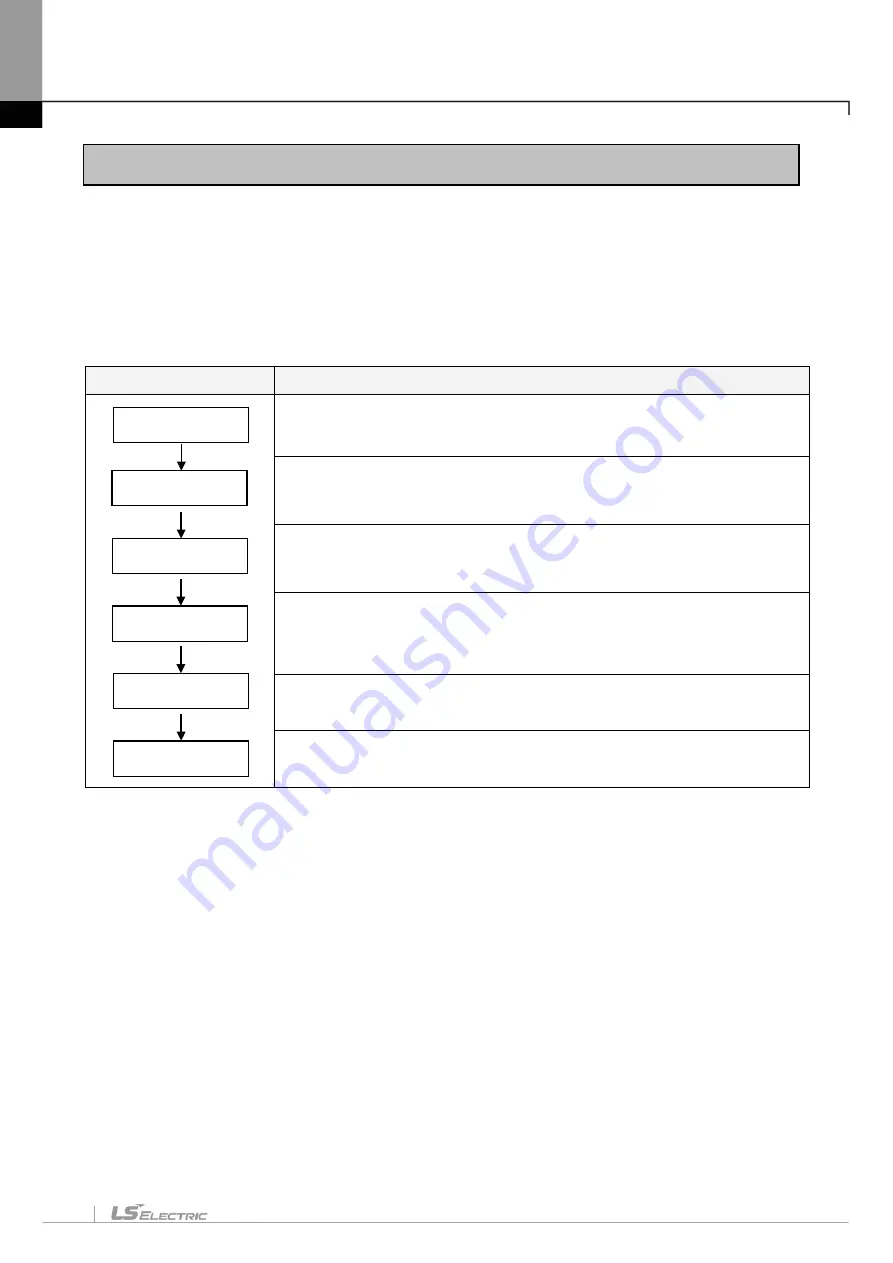
Trace Data operates as follows;
Sequence
Details
Confirm the connection with PLC and the Run status of PLC.
Decide to allow trace or not, And specify trigger condition, sample properties
and trace device. Refer to 11.8.3 for more details.
Write trace setting items on PLC. Refer to 1) Write Trace Setting Items in
11.8. 5 for more details.
Start trace with specified trigger conditions automatically or with manual trace
selected. Refer to 11.8.3 Setting Trace for detailed trigger setting, and 4) Start
Manual Trace in 11.8.5 for detailed manual trace.
Read trace data from PLC. Refer to 3) Read Trace in 11.8.5 for more details
Refer to 11.8.4 for more details.
[Sequence]
1. Select [Monitor]-[Data Traces] on the menu.
Setting Trace
Write to PLC
Ready
Start Trace
Read Data
Process Graph
Summary of Contents for XGT Series
Page 7: ...Safety Instruction 6 ...
Page 11: ...About User s Manual 2 ...
Page 34: ...Chapter 1 Introduction 1 9 11 Wait a second for the installation to be complete ...
Page 47: ...Chapter 1 Introduction 1 22 ...
Page 69: ...Chapter 2 Basic Application 2 22 ...
Page 74: ...Chapter 2 Basic Application 2 27 ...
Page 91: ...Chapter 2 Basic Application 2 44 ...
Page 118: ...Chapter 3 Project 3 27 Dialog Box a b c d f e h g ...
Page 154: ...Chapter 3 Project 3 63 ...
Page 156: ...Chapter 3 Project 3 65 3 Specify the communication module in the I O parameters ...
Page 171: ...Chapter 3 Project 3 80 ...
Page 174: ...Chapter 4 Variable Comment 4 3 4 1 3 View flag Dialog Box Description of Dialog Box a b c d ...
Page 192: ...Chapter 4 Variable Comment 4 21 ...
Page 197: ...Chapter 4 Variable Comment 4 26 ...
Page 203: ...Chapter 4 Variable Comment 4 32 5 Save the EtherNet IP variable as CSV file ...
Page 218: ...Chapter 4 Variable Comment 4 47 Dialog box ...
Page 219: ...Chapter 4 Variable Comment 4 48 ...
Page 221: ...Chapter 4 Variable Comment 4 50 ...
Page 269: ...Chapter 5 LD Edit 5 48 ...
Page 297: ...Chapter 6 IL Edit 6 28 3 Click Go To ...
Page 331: ...Chapter 8 Find Replace 8 4 Note Advanced Button is pressed ...
Page 344: ...Chapter 8 Find Replace 8 17 ...
Page 354: ...Chapter 8 Find Replace 8 27 ...
Page 363: ...Chapter 8 Find Replace 8 36 ...
Page 365: ...Chapter 8 Find Replace 8 38 ...
Page 455: ...Chapter 10 Online 10 60 4 If you press OK the changed items are displayed ...
Page 482: ...Chapter 10 Online 10 87 ...
Page 487: ...Chapter 10 Online 10 92 ...
Page 603: ...Chapter 11 Communication and Special Function Blocks 11 116 ...
Page 625: ...Chapter 13 Online Editing 13 4 ...
Page 635: ...Chapter 14 Print 14 10 ...
Page 690: ...Chapter 16 SFC Edit 16 25 3 Move cursor to the area to paste to 4 Select menu Edit Paste ...
Page 715: ...Chapter 17 ST Edit 17 8 Dialog ...
Page 731: ...Chapter 17 ST Edit 17 24 ...
Page 763: ...Chapter 18 Exclusive Functions for Event Input Module 18 32 ...
Page 766: ...Chapter 19 User Function Function Block 19 3 h g a b c d e f Dialog box ...
Page 773: ...Chapter 19 User Function Function Block 19 10 ...
Page 783: ...Chapter 19 User Function Function Block 19 20 ...
Page 801: ...Chapter 20 LS Studio 20 18 7 After setting the save area select the OK button ...
Page 803: ...Warranty and Environment Policy 2 ...