SDA Operator’s Manual
As shown in Figure 2, the initial output and the output of the digital phase detector are set to zero.
The next time value output is equal to the nominal data rate. This value is fed back to the
comparator on the far left which compares this time value to the measured time of the next data
edge from the digital phase detector. The difference is the error between the data rate and the
recovered clock. This difference is filtered and added to the initial base period to generate the
corrected clock period. The filter controls the rate of this correction by scaling the amount of error
that is fed back to the clock period computation. This filter is implemented in the SDA as a single-
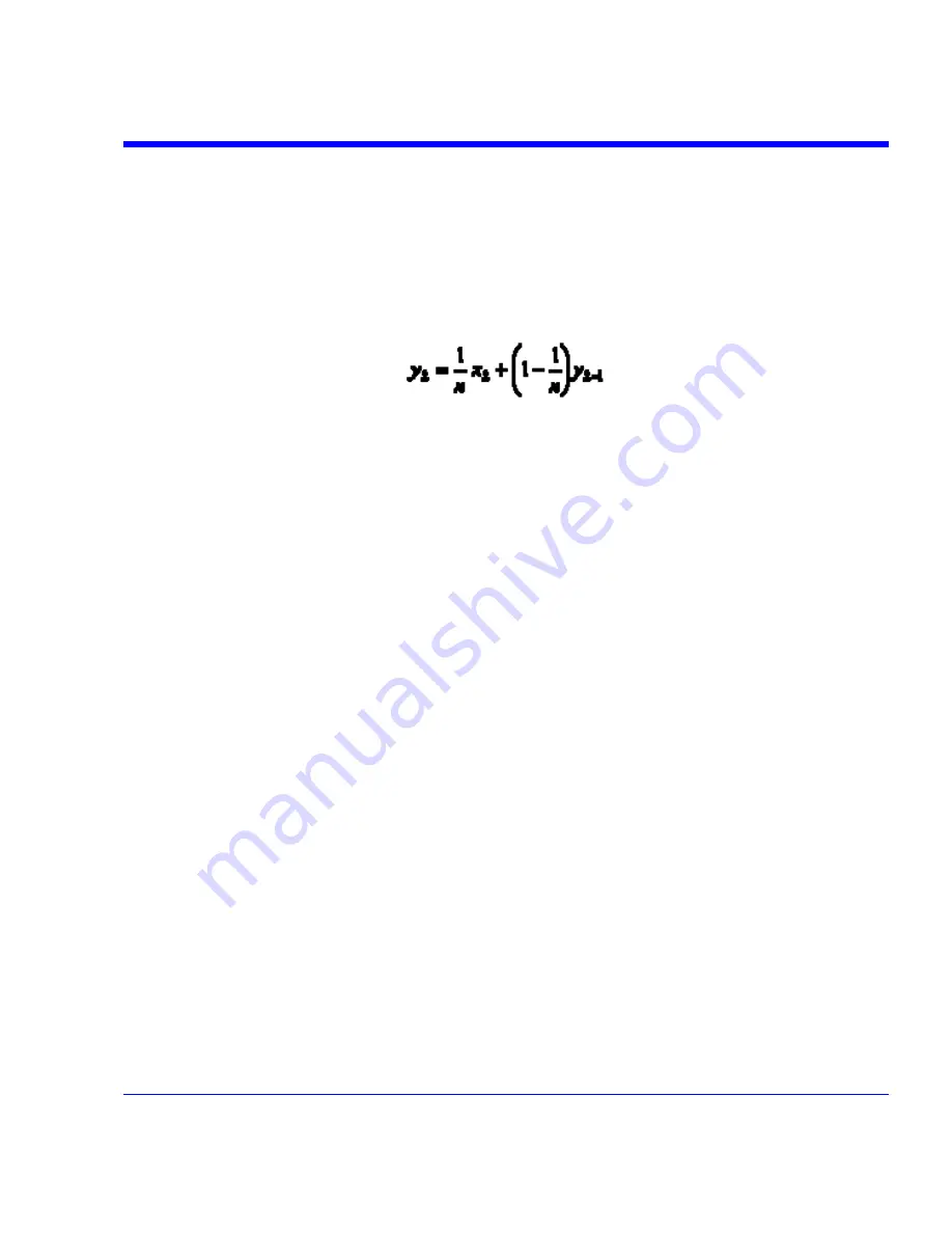
pole infinite impulse response (IIR) low-pass filter. The equation of this filter is:
The value of
y
k
is the correction value for the
k
th
iteration of the computation and
x
k
is the error
between the
k
th
data edge and the corresponding clock edge. Note that the current correction
factor is equal to the weighted sum of the current error and all previous correction values. The
multiplier value is set to one in the SDA, and the value of n is the PLL cutoff divisor that is set
from the SDA main menu. The cutoff frequency is Fd/n where Fd is the data rate. This filter is
related to its analog counterpart through a design process known as impulse invariance and is
only valid for cutoff frequencies much less than the data rate. For this reason, the minimum PLL
cutoff divisor setting is 20 in the SDA.
The factor
n
determines the number of previous values of the correction value
y
that is used in
the computation of the current correction value. This is theoretically infinite; however, practically
there is a limit to the number of past values included. One can define a “sliding window”
equivalent to a number of UI (unit intervals) of the data signal for a given value of
n
. This is useful
for measuring signals such as serial ATA and PCI-Express, where the specifications call for clock
recovery over a finite window. The equivalent bandwidth of the sliding window is given by a
sin(x)/x function. The first null of this function occurs at x =
π
or ½ the bit rate (the digital
equivalent of the frequency of a signal at the sampling rate is 2
π
and the sampling rate for clock
recovery is the data rate). This is scaled by the window size to be 2
π
/ N where N is the window in
UI. The 3 dB point of the sin(x)/x function is at 0.6
π
/ N or 0.3Fd/N for a window length of
N
. This
gives us a relationship between
N
and
n
:
Fd/n = 0.3Fd/N or n = N/0.3
For a sliding window size of 250, the equivalent value of
n
would be 833.
SDA-OM-E Rev H
367
Summary of Contents for SDA
Page 1: ...SERIAL DATA ANALYZER OPERATOR S MANUAL December 2007 ...
Page 223: ...SDA Operator s Manual Example 6 SDA OM E Rev H 223 ...
Page 225: ...SDA Operator s Manual SDA OM E Rev H 225 ...
Page 246: ...246 SDA OM E Rev H ...
Page 247: ...SDA Operator s Manual Excel Example 5 Using a Surface Plot SDA OM E Rev H 247 ...
Page 279: ...SDA Operator s Manual Convolving two signals SDA OM E Rev H 279 ...
Page 310: ...The jitter wizard is accessed from the Analysis drop down menu 310 SDA OM E Rev H ...
Page 327: ...SDA Operator s Manual SDA OM E Rev H 327 ...
Page 328: ...328 SDA OM E Rev H ...
Page 394: ...394 SDA OM E Rev H ...


