background image


Istruzioni per l'utente 


279 


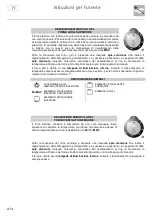
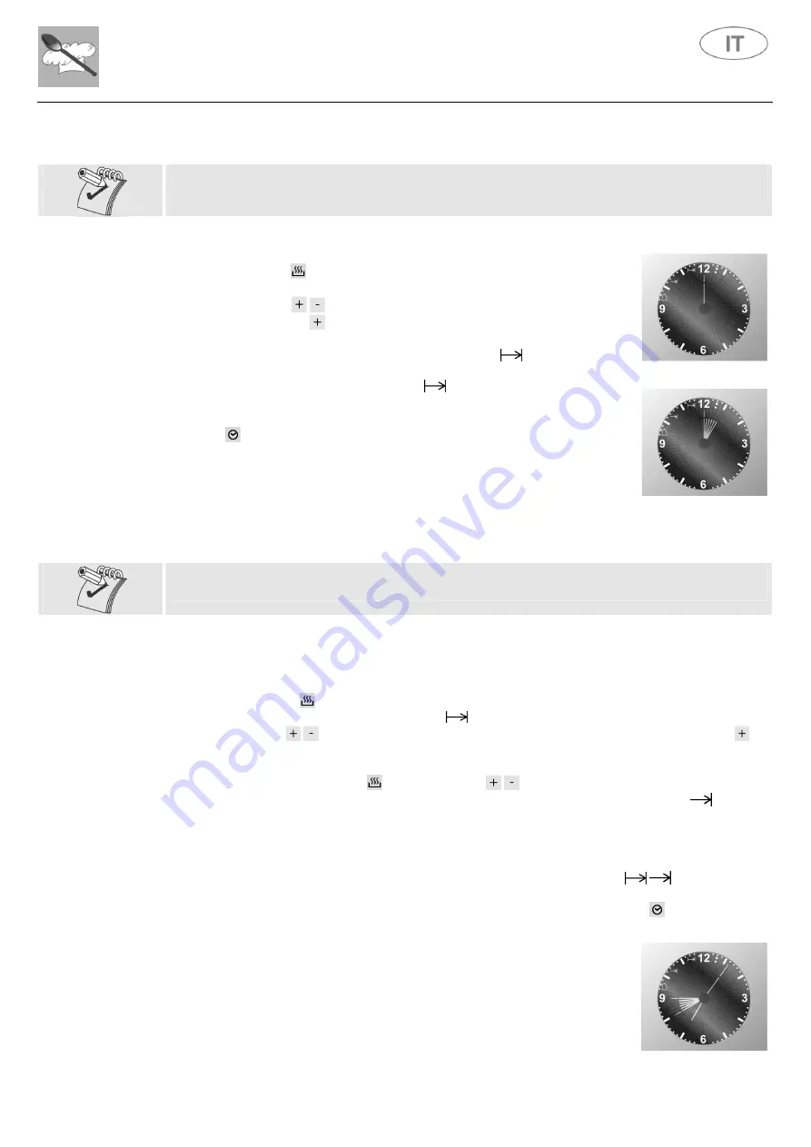
PROGRAMMAZIONE DELLA DURATA DI COTTURA 


Questa funzione consente di programmare la durata di cottura per spegnere automaticamente 
il forno al termine della cottura.


Fig. 3 


  Impostare la funzione di cottura prescelta e la temperatura agendo sulle 

apposite manopole di controllo; 

  premere il tasto   per entrare nel menù di programmazione, il display si 

illuminerà come mostrato in 

Fig. 3

;  

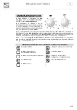
  agire  sui  tasti 

/   per  impostare  la 

durata  di  cottura

,  ad  ogni 

pressione del tasto   si aggiungerà 

un minuto

 di cottura ed ogni 

dodici 

minuti

  si  illuminerà 

un  segmento  interno

  (

Fig.  4

).  Dopo 

7  secondi

  il 

programma di cottura parte e si accende il simbolo 

Al  termine del tempo di cottura programmato verrà emesso un allarme 

acustico  per

  7  minuti

,  il  simbolo 

  ed  i  numeri  del  quadrante 

inizieranno a lampeggiare 

spegnendo automaticamente

 il forno;  

  premere  un  tasto  qualunque  per  interrompere  il  segnale  acustico  o  il 

tasto   per cancellare il programma. 


Fig. 4 


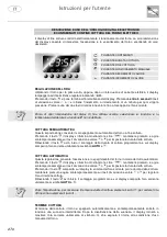
PROGRAMMAZIONE DELLA DURATA DI COTTURA E DI FINE COTTURA 


Questa funzione serve a programmare l’accensione del forno ad un’ora prefissata ed il suo 
spegnimento automatico al termine della cottura.


Impostare  la  funzione  di  cottura  prescelta  e  la  temperatura  agendo  sulle  apposite  manopole  di 

controllo.  


Oltre ad impostare la durata della cottura, definire anche l’ora di accensione del forno: 


  premere  il  tasto 

  per  entrare  nel  menù  di  programmazione,  il  display  si  illuminerà  come 

mostrato in 

Fig. 3

 e si accende il simbolo 

  agire  sui  tasti 

/   per  impostare  la 

durata  di  cottura

,  ad  ogni  pressione  del  tasto 

  si 

aggiungerà 

un  minuto

  di  cottura  ed  ogni 

dodici  minuti

  si  illuminerà 

un  segmento  interno


(

Fig. 4

); 

  premere nuovamente il tasto   ed agire sui tasti  /  per definire l’orario di 

fine cottura

 (orario 

di fine cottura meno durata di cottura = orario di inizio cottura), si accende il simbolo 

Dopo 

7 secondi

 il display visualizzerà l’orario corrente mostrando l’ora di 

inizio cottura

 e la 

durata  di  cottura

  mediante  l’illuminazione  dei 

segmenti  interni

  che  resteranno 

fissi

  fino 

all’inizio della cottura e 

lampeggeranno

 per tutto il tempo di durata della cottura. 

All’ora  impostata  il  forno  si 

accenderà


automaticamente

;  al    termine  del  tempo  di  cottura 

programmato verrà emesso un allarme acustico per

 7 minuti

, i simboli 


 ed i numeri del 

quadrante inizieranno a lampeggiare 

spegnendo automaticamente

 il forno; 

  premere un tasto qualunque per interrompere il segnale acustico o il tasto   per cancellare il 

programma. 


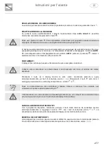
In 

Fig.  5

  è  riportato  un  esempio  di  programmazione:  l’ora  corrente  è  7:06, 

l’inizio cottura è programmato per le 8 e il termine alle 9. 


Quando saranno le 8 i 

segmenti


interni

 compresi tra 8 e 9 cominceranno a 

lampeggiare e resterà fissa la 

lancetta

 delle ore. 


Fig. 5 

Summary of Contents for MAESTRO

Page 1: ...Gebruiksaanwijzing Gebrauchsanweisung Manuel d utilisation Manuale d uso Instruction manual...

Page 2: ......

Page 3: ...NEDERLANDS 5 83 DEUTSCH 85 163 FRAN AIS 165 243 ITALIANO 245 323 ENGLISH 325 403...

Page 4: ...aties gedurende verloop van tijd onveranderlijk te houden Elke afzonderlijke paragraaf leidt U trapsgewijze naar een nauwkeurige kennis van de kookplaat de tekst is gemakkelijk verstaanbaar wegens de...

Page 5: ...______________________________________________________ 30 6 Gebruik van de kookplaat _________________________________ 41 6 1 Inschakeling van de branders _____________________________________________...

Page 6: ...lingen voor een correct gebruik van de fry top vleesrooster________________ 67 13 4 Aanbevelingen voor een correct gebruik van de grill met vulkanisch gesteente ________ 67 13 5 Aanbevelingen voor een...

Page 7: ...tussen twee meubels bestaande uit een stuk maar waar de zijkanten steeds toegankelijk blijven 1 Algemene aanwijzingen Dit product is gefabriceerd conform de volgende richtlijnen en verordeningen 2014...

Page 8: ...HILLENDE AFVALMATERIALEN VAN DE VERPAKKING EN BRENG DEZE NAAR HET DICHTBIJ GELEGEN CENTRUM VOOR HET INZAMELEN VAN GESCHEIDEN AFVAL DE AARDVERBINDING IS VERPLICHTEND EN MOET VOLGENS DE BESTAANDE VEILIG...

Page 9: ...AKELING VERMIJD HET EVENEENS DE VERHITTINGSELEMENTEN VAN DE OVEN AAN TE RAKEN INDIEN MEN ZICH OP DE OPEN OVENDEUR DE SCHUIFLADEN OF DE OPBERGRUIMTE ZET OF LEUNT KAN DIT HET OMSTOTEN VAN HET TOESTEL VE...

Page 10: ...Aanwijzingen voor de installateur 10 3 Installatie AFMETINGEN VAN DE TOP PLATEN mm SINTESI GENESI ASCOT AFMETINGEN VAN DE FORNUIZEN mm SINTESI...

Page 11: ...Aanwijzingen voor de installateur 11 GENESI ASCOT...

Page 12: ...aterpas op de vloer te zetten Door ze overmatig los te draaien wordt het fornuis instabiel Om het fornuis te verhogen wordt aangeraden om de standaard pootjes te vervangen door andere hogere pootjes b...

Page 13: ...voor de montage Kantel het fornuis naar achteren Laat sierlijst A de montagezitting naderen zoals het kader in de afbeelding toont Breng de sierlijst aan op een wijze dat deze in aanslag op de montage...

Page 14: ...e van het fornuis bevinden detail 2 3 5 Montage opstaande rand optioneel De opstaande rand mag niet gebruikt worden in combinatie met een roestvrijstalen achterwand Handel als volgt voor de montage Br...

Page 15: ...oven aanwezig zijn Breng de telescoopgeleiders in positie op de gewenste hoogte door de bovenzijde vast te haken aan het frame detail 1 Draai de geleider vervolgens om de vastkoppeling aan de onderka...

Page 16: ...ervan verzekeren dat de begrenzerklep en de huishoudelijke installatie de elektrische lading van het toestel kunnen dragen De geel groene geaarde kabel mag niet onderbroken worden De elektrische kabel...

Page 17: ...TE PLAAT VERMOGEN kW VOEDING BOVENSTE PLAAT 4 6 8 BRANDERS 0 006 BOVENSTE PLAAT 4 6 BRANDERS B T C 2 4 BOVENSTE PLAAT 4 6 BRANDERS F 2 2 BOVENSTE PLAAT 4 6 BRANDERS G 2 5 BOVENSTE PLAAT 4 BRANDERS B T...

Page 18: ...OVENS B T C 6 0 FORNUIS 4 BRANDERS 2 OVENS F 5 8 FORNUIS 4 BRANDERS 2 OVENS G 6 1 FORNUIS 6 BRANDERS 2 OVENS M 4 3 FORNUIS 6 BRANDERS 2 OVENS B T C 6 7 FORNUIS 6 BRANDERS 2 OVENS G 6 9 FORNUIS 4 BRAN...

Page 19: ...11 0 SCHEMA C FORNUIS 2 OVENS VERMOGEN kW VOEDING FORNUIS 6 BRANDERS 2 OVENS 4 5 FORNUIS 8 BRANDERS 2 OVENS 5 1 FORNUIS 4 BRANDERS 2 OVENS M 4 5 FORNUIS 4 BRANDERS 2 OVENS B T 6 9 FORNUIS 6 BRANDERS...

Page 20: ...n de klem aangesloten en moet langer zijn dan 20 mm t o z de lijngeleiders De neutrale blauwe leiding wordt aangesloten aan de klem met de merking N De lijngeleider wordt aangesloten aan de klem met d...

Page 21: ...cht te worden die de verbruikte lucht op een natuurlijke wijze en rechtstreeks ontlast d m v een verticale rechtlijnige leiding met een lengte van twee keer de diameter en een minimum doorsnede van 10...

Page 22: ...ES FI FR GB IE IT NL NO PT SE Voor butaan en propaan gas moet een drukregelaar voorzien worden in overeenkomst met de geldende normen De pakkingen dienen in overeenkomst met de geldende normen te zijn...

Page 23: ...d Snijdende voorwerpen scherpe punten enz Vermijden De buizen nooit in aanraking met bestanddelen laten komen die hogere temperaturen dan 70 C kunnen bereiken De buizen langs de hele doorloop controle...

Page 24: ...en wordt ook het nieuwe etiket meegeleverd Alles weer hermonteren in omgekeerde volgorde t o z van de demontering en er zorg voor dragen de vlamschermen correct op de brander aan te brengen 3 11 1 Min...

Page 25: ...NDER MAX MIN MAX 121 SNEL A 3000 750 332 l h 94 HALF SNEL B 1750 480 194 l h 72 HULP C 1000 330 111 l h 150 DRIEVOUDIGE KROON D 3500 1400 388 l h 69 E1 102 E2 DUO WOKBRANDER E1 E2 4500 300 498 l h G25...

Page 26: ...G EE 120 EE 120 56 3 B T C F G 56 8 B T C F G EE 120 57 2 B T C F G B VLEESROOSTER C PLAAT IN VUURVAST AARDEWERK G GRILL T FRY TOP F FRITUURPAN EE TYPE BRANDER SNEL A 59 2 HALF SNEL B 59 9 HULP C DRIE...

Page 27: ...S mbar GASSPROEIER N TYPE BRANDER MAX MIN MAX 121 SNEL A 3000 750 332 l h 94 HALF SNEL B 1750 480 194 l h 72 HULP C 1000 330 111 l h 135 WOKBRANDER G 3500 1800 387 l h G25 G25 3 AARDGAS 25 68 H1 137 H...

Page 28: ...120 EE 120 55 1 55 2 B T EE 120 EE 120 55 5 B T C F G 56 B T C F G B VLEESROOSTER C PLAAT IN VUURVAST AARDEWERK G GRILL T FRY TOP F FRITUURPAN EE TYPE BRANDER SNEL A 58 4 HALF SNEL B 56 5 HULP C WOKB...

Page 29: ...instelbare voeten die er eerder op vastgeschroefd werden Indien het nodig is het toestel te verplaatsen dan moeten de voeten tot het einde toe vastgeschroefd worden en pas ingesteld worden na afloop v...

Page 30: ...HTERSTE RECHTS ACHTERSTE IN HET MIDDEN LINKS ACHTERSTE IN HET MIDDEN RECHTS VOORSTE IN HET MIDDEN ACHTERSTE IN HET MIDDEN VOORSTE INHET MIDDEN LINKS VOORSTE IN HET MIDDEN RECHTS VOORSTE LINKS VOORSTE...

Page 31: ...controlelampje duidt het verwarmingsproces aan GRILL twee lichtgevende controlelampjes leveren fundamentele informaties betreffend de werking van het toestel Het inschakelen van het groen controlelamp...

Page 32: ...past Draai aan de knop om de gewenste vermogenswaarde in te stellen zie de tabel in paragraaf 11 3 Door aan de knop te draaien zal op het betreffende display het daadwerkelijke gewenste vermogensnivea...

Page 33: ...INGSELEMENTEN VENTILATOR BOVENSTE VERWARMINGSELEMENT VERWARMINGSELEMENT CONVECTIE ONDERSTE VERWARMINGSELEMENT ONTDOOIEN GRILL ELEMENT BESCHRIJVING VAN DE KNOP VOOR DE ELEKTRISCHE HULPOVEN Sommige keuk...

Page 34: ...erlichting Tijdens de werking brandt de lamp altijd wilt u de lamp gebruiken wanneer de oven uitgeschakeld is tijdens de reiniging bijvoorbeeld dan moet de knop op het symbool gedraaid worden BESCHRIJ...

Page 35: ...dt het bereiken van de ingestelde temperatuur aan Het achtereenvolgens aan en uit gaan van het oranje controlelampje duidt op de automatische inwerkingtreding van de verwarming om de temperatuur binne...

Page 36: ...oor het drukken van toets verlicht zich het display en geeft de nummers aan hou de toets gedrukt en handel tegelijkertijd op de toetsen voor de waardeverandering of om de kooktijd in te stellen Wannee...

Page 37: ...erking op het einde van de ingestelde tijd Door het drukken van de toets verschijnt op het display de cijfers hou hem gedrukt en handel tegelijkertijd op de toetsen voor de waardeverandering of Door d...

Page 38: ...tie over te gaan door op de toets te drukken Kies de Manuale functie als u geen kookprogramma s wilt gebruiken PROGRAMMERING VAN DE MINUTENTELLER Deze functie dient voor het inschakelen van een alarmt...

Page 39: ...akeling van de oven in Druk op de toets om het programmeermenu binnen te gaan het display zal oplichten zoals getoond wordt in Afb 3 en het symbool wordt ingeschakeld Gebruik de toetsen om de kookduur...

Page 40: ...ren drukt u minstens 7 seconden op de toets Bij iedere extra druk op de toets zal van toon veranderd worden HELDERHEID Het is mogelijk om de helderheid van de klok te wijzigen Druk gelijktijdig minste...

Page 41: ...n de branders in te schakelen druk op de knop in overeenstemming met de gekozen brander en draai deze tegen de klok tot aan de minimumpositie Door de knop gedrukt te houden wordt het automatische insc...

Page 42: ...eersysteem S naar links te plaatsen zoals aangegeven in de afbeelding Trek het frituurbekken uit verwijder het zeepsop spoel het bekken onder stromend water Droog het bekken af en plaats het in zijn o...

Page 43: ...frituurvloeistof de ingestelde waarde overschrijdt kan dit toestel de verwarming uitschakelen beide controlelampjes schakelen zich uit Om de verwarming van de frituurpan terug in te schakelen moet de...

Page 44: ...ijtende of verbrande geur ontwikkeld worden ontstaan door eventuele olieachtige overblijfselen gedurende de fabricatie die onaangename geuren en smaken aan het koken zouden kunnen afgeven Om deze onge...

Page 45: ...edrijfstelling Als volgt te werk gaan Verplaats de grill in gietijzer heel voorzichtig omdat hij tegen stoten breekbaar is Til het verwarmingselement op en blokkeer het door het blokkeersysteem S naar...

Page 46: ...te plaatsen Breng de knop van de regelaar naar het minimum vermogen 1 Plaats de multifunctionele pot met de te koken etenswaren op de grill in gietijzer Plaats het deksel terug op de pot zodat de voch...

Page 47: ...diameter betrekt 10 2 Inschakeling Plaats de pot of braadpan met de te koken etenswaren op het uitgekozen verwarmingsonderdeel Draai de knop van de energieregelaar op de gewenste positie na enkele mi...

Page 48: ...niet gecompromitteerd wordt door het inductieveld waarvan de frequentie tussen 20 en 50 kHz ligt Vermijd het metalen voorwerpen en sieraden te dragen die rechtstreeks in aanraking met het lichaam kom...

Page 49: ...stralingselementen links A en de twee rechts B A B STRALINGSELEMENT 1 180 2 145 3 210 VERMOGEN W 1850 1400 2300 VERMOGEN MET BOOSTER FUNCTIE W zie paragraaf 11 6 3 3000 2200 3700 TOTAAL MAXIMUMVERMOGE...

Page 50: ...stelde waarde handhaaft ten koste van de andere eerder ingestelde elementen die inderdaad een daadwerkelijke vermogensafname kunnen ondergaan Door namelijk het laatste stralingselement te activeren zu...

Page 51: ...met meer of minder water bereiding van jams enz 9 Gebraad van vlees of vis biefstukken lever aanbraden van vlees en vis eieren enz P Frituren in olie van aardappels enz snel aan de kook brengen van wa...

Page 52: ...het stralingselement dan weer opnieuw te kunnen gebruiken moet de betreffende knop eerst op stand 0 gezet worden en moet opnieuw een nieuwe gewenste vermogenswaarde ingesteld worden Als een knop op o...

Page 53: ...lement Alvorens een stralingselement te activeren zet u een geschikte pan op de betreffende kookcirkel Door ongeacht welke knop met de wijzers van de klok mee te draaien zal een geluidssignaal klinken...

Page 54: ...et worden anders zal het symbool dat op het display weergegeven wordt vervangen worden door foutcode die de deactivering van het stralingselement aangeeft om het stralingselement opnieuw in te stellen...

Page 55: ...n mechanische klik verkregen wordt samen met een geluidssignaal tot positie P en houd de knoppen minstens 2 seconden in deze positie op de overeenkomstige displays worden de symbolen hiernaast weergeg...

Page 56: ...gselement buiten te sluiten in geval van een storing of een slechte werking van dat element Nadat de geautoriseerde Technische Assistentiedienst het stralingselement gerepareerd heeft zal het mogelijk...

Page 57: ...defecten en storingen Als een defecte werking geconstateerd wordt schakel het apparaat dan uit en sluit het af van het elektriciteitsnet Probeer niet het defecte stralingselement opnieuw te gebruiken...

Page 58: ...geduid wordt in paragraaf 11 5 Het display toont het symbool hiernaast De knop staat niet op de correcte stand Het is niet nodig de Assistentiedienst te bellen om het stralingselement opnieuw in te st...

Page 59: ...nde punten gecontroleerd worden Of zich een stroomonderbreking voorgedaan heeft Indien na de hernieuwde start van het kookprogramma de blokkering zich opnieuw voordoet betekent dit dat de veiligheidsv...

Page 60: ...cties in positie 0 of op de functie open de deur in twee tijden laat ze gedurende 4 5 seconden half open ca 5 cm om ze dan volledig te openen Indien men op de etenswaren dient in te grijpen open de de...

Page 61: ...oktijd opent u de ovendeur en neemt u de stang van het draaispit eruit met behulp van de plastic handgreep D die op de basis van stang A geschroefd moet worden 12 4 7 Het ontdooien Draai de knop van d...

Page 62: ...nctiekeuze in positie draai de thermostaatknop in overeenstemming met de gewenste temperatuurwaarde 12 5 5 Koken met stoom De stoomgenerator bereikt zeer hoge temperaturen giet alleen mineraalwater of...

Page 63: ...emde gat C dat zich in de ovenwand bevindt Voordat u de ovendeur sluit controleert u of stang A correct in gat C geplaatst is steek de stang naar binnen door hem licht met de wijzers van de klok mee e...

Page 64: ...innen vanonder De positie van de bordenhouder grill kan volgens de persoonlijk smaak en de verschillende kookvereisten veranderd worden Voor het bakken dient een voorverwarming van ongeveer 5 minuten...

Page 65: ...te voegen verwarm de oven aan maximumtemperatuur gedurende 30 40 minuten met gesloten deur en wacht tot het ophouden van de rook en de geuren Om te voorkomen dat de eventuele damp in de oven last ver...

Page 66: ...n in te schakelen moet de knop op een temperatuur tussen 50 C en MAX gedraaid worden of op de gewenste functie 12 8 2 Koken met de grill met gesloten deur Draai de knop op en laat de grill oven circa...

Page 67: ...zingen in paragraaf 14 8 1 Ontlading van de frituurvloeistof Om gevaarlijke verbranding met het frituurvloeistof te vermijden schakel niet de open vlammen in die zich in de nabijheid van de frituurpan...

Page 68: ...van een goed rendement en een adequaat energieverbruik is het absoluut van belang alleen recipi nten te gebruiken die geschikt zijn voor inductiekoken De diameter van de bodem van de recipi nten moet...

Page 69: ...ktijdige realisatie van verschillende gerechten toe Men kan koekjes en kleine pizza s op drie verschillende ovenschalen koken De oven kan echter ook gebruikt worden voor het koken op n enkele ovenscha...

Page 70: ...moet tenminste 1 kg wegen De rode malse vleessoorten rosbief filet enz of de vleessoorten die van buiten goed gekookt dienen te zijn maar hun sap binnenin dienen te bewaren vragen een koken aan een a...

Page 71: ...180 180 180 180 180 30 45 20 OVENSCHOTELS OVENSCHOTEL VAN PASTA OVENSCHOTEL VAN GROENTEN ZOETE EN GEZOUTEN SOUFFL S PIZZA EN GEVULDE PIZZA 2 2 0 75 0 5 1 3 1 3 1 3 1 3 2 2 2 2 185 185 180 200 200 200...

Page 72: ...120 20 30 0 5 L VIS VISOVENSCHOTEL 2 180 30 40 0 3 L GROTE VISSEN TOT 300 g 2 160 170 20 30 0 3 L VISFILET 2 150 160 15 25 0 2 L HELE VIS TOT 1000 g 2 160 170 40 50 0 5 L komt overeen met de positie v...

Page 73: ...AGNOTTA S 1 2 2 2 40 190 200 20 25 20 25 0 3 L FOCACCIABROOD 1 2 2 2 40 200 20 30 25 35 0 3 L EMPANADA S 1 2 2 2 40 200 20 30 25 35 0 4 L BROODDEEG 750 1000 g 1 2 2 2 40 220 15 25 10 15 0 3 L BROODDEE...

Page 74: ...ijd producten met schurende substanties schuursponsen stalen of zure wollen die de oppervlakken kunnen beschadigen Vermijd zure of alkaline substanties op de email achter te laten citroensap azijn zou...

Page 75: ...blijfselen dienen met een houten stokje of een naald te worden verwijderd Let er echter op het keramisch isolatieonderdeel niet te beschadigen 14 8 Reiniging van de frituurpan 14 8 1 Ontlading van de...

Page 76: ...tenslotte de plaat in vuurvast aardewerk V met specifieke producten Droog volledig af en plaats de plaat van de fry top vleesrooster terug in zijn positie 14 10 Reinig van de grill met vulkanisch gest...

Page 77: ...e plaat in vuurvast aardewerk De plaat in vuurvast aardewerk moet geregeld gereinigd worden beter nog na ieder gebruik wanneer de controlelampjes van de overblijvende warmte uitgeschakeld zijn Eventue...

Page 78: ...rs Let op dat het warme vlak van keramisch glas niet in aanraking komt met plastic aluminiumfolie suiker of voedsel dat suiker bevat Deze substanties kunnen het oppervlak van het vlak schade berokkene...

Page 79: ...dig met een propere doek af 14 13 1 Reiniging van de ovenwanden Voor de reiniging van dit type ovens mogen nooit reinigingsproducten gebruikt worden De ovenwanden kunnen gereinigd worden met witte azi...

Page 80: ...m te demonteren of kunt u zich in speciale gevallen tot het dichtstbijzijnde Assistentiecentrum te richten Ga als volgt te werk om de deur te demonteren Open de ovendeur en haak de beveiligingen van d...

Page 81: ...r moeten de beveiligingen van de scharnieren altijd opnieuw in werking worden gesteld 15 2 Verwijdering van de ondersteuningsframe aan de zijkanten De ondersteuningsframes aan de zijkanten kunnen wegg...

Page 82: ...Gebruik in geen geval schurende of corroderende reinigings middelen poederproducten of metaalsponsjes Spoel de ventilator af en droog hem zorgvuldig Monteer opnieuw de ventilator en het afdekcarter d...

Page 83: ...t deksel van de achterste pen te bevrijden detail 2 neem moer B opnieuw vast til deksel C op duw hem een beetje naar achteren pijlen b c en verwijder het deksel volledig uit voorgeleider D detail 3 Re...

Page 84: ...ch Anweisung dieses Handbuches erlauben die dauerhafte Erhaltung der Betriebsleistungen des Herdes Die einzelnen Abschnitte sind so aufgebaut dass sie Schritt f r Schritt alle Funktionalit ten des Her...

Page 85: ...________________________________________________________ 110 6 Bedienung der Kochfl che _______________________________ 121 6 1 Anz nden der Brenner ___________________________________________________...

Page 86: ...3 3 Ratschl ge zum korrekten Gebrauch des Fry top Barbeque Grill _________________ 147 13 4 Ratschl ge zur korrekten Gebrauch des Vulkansteingrills ________________________ 147 13 5 Ratschl ge zum kor...

Page 87: ...h so installiert werden kann dass die Seitenw nde zug nglich sind 1 Allgemeine Informationen Dieses Produkt wurde in bereinstimmung mit folgenden Richtlinien und Verordnungen hergestellt 2014 35 EU be...

Page 88: ...ICHT UNBEAUFSICHTIGT IM H USLICHEN BEREICH HERUMLIEGEN TRENNEN SIE DIE VERSCHIEDENEN ABFALLMATERIALIEN AUS DER VERPACKUNG UND ENTSORGEN SIE DIESE AN DER N CHSTEN GEEIGNETEN SAMMELSTELLE DER ERDSCHLUSS...

Page 89: ...E DES OFENS DAS ABST TZEN ODER SETZEN AUF DIE OFFENE OFENT R DIE SCHUBLADEN ODER DAS ABLAGEFACH K NNEN ZUM UMKIPPEN DES GER TS F HREN MIT DARAUS FOLGENDER GEFAHR F R PERSONEN DIE SCHUBLADEN HABEN EINE...

Page 90: ...Anweisungen f r den Installateur 90 3 Installation ABMESSUNGEN DER KOCHMODULE mm SINTESI GENESI ASCOT ABMESSUNGEN DER HERDE mm SINTESI...

Page 91: ...Anweisungen f r den Installateur 91 GENESI ASCOT...

Page 92: ...enregulierung sodass der Herd am Fu boden nivelliert wird Bei zu starkem Aufschrauben der St tzf e verliert der Herd an Standfestigkeit Zur Erh hung des Herdes empfiehlt es sich die Standard St tzf e...

Page 93: ...ehen Neigen Sie den Herd nach hinten N hern Sie die Leiste A dem Montagesitz wie im Bildausschnitt zu sehen Setzen Sie die Leiste so ein dass der Anschlag mit dem Montagesitz erhalten wird Ziehen Sie...

Page 94: ...n Detail 2 3 5 Montage des Spritzschutzes Sonderzubeh r Der Spritzschutz darf nicht in der Kombination mit der Edelstahlr ckwand verwendet werden Bei der Montage ist wie folgt vorzugehen St tzen Sie d...

Page 95: ...n Zubeh rteile Positionieren Sie die Teleskopf hrung auf der gew nschten H he und h ngen Sie die obere Seite am Rahmen ein Detail 1 Drehen Sie die F hrung anschlie end bis sie an der Unterseite einhak...

Page 96: ...n Sie sicher dass das Begrenzungsventil sowie die Hausanlage f r die elektrische Leitungsaufnahme des Ger tes ausgelegt sind Das gelb gr ne Erdkabel darf keine Unterbrechungen aufweisen Das Elektrokab...

Page 97: ...N DAS KLEMMENBRETT TOP KOCHFL CHE LEISTUNG kW STROMVERSORGUNG TOP KOCHFL CHE 4 6 8 BRENNER 0 006 TOP KOCHFL CHE 4 6 BRENNER B T C 2 4 TOP KOCHFL CHE 4 6 BRENNER F 2 2 TOP KOCHFL CHE 4 6 BRENNER G 2 5...

Page 98: ...RD 4 BRENNER 2 FEN B T C 6 0 HERD 4 BRENNER 2 FEN F 5 8 HERD 4 BRENNER 2 FEN G 6 1 HERD 6 BRENNER 2 FEN M 4 3 HERD 6 BRENNER 2 FEN B T C 6 7 HERD 6 BRENNER 2 FEN G 6 9 HERD 4 BRENNER 2 FEN M B T C 6 8...

Page 99: ...FEN 5 ELEMENTE 11 0 SCHEMA C HERD 2 FEN LEISTUNG kW STROMVERSORGUNG HERD 6 BRENNER 2 FEN 4 5 HERD 8 BRENNER 2 FEN 5 1 HERD 4 BRENNER 2 FEN M 4 5 HERD 4 BRENNER 2 FEN B T 6 9 HERD 6 BRENNER 2 FEN M 5 0...

Page 100: ...n die Klemme zu legen und muss zirka 20 mm l nger bez glich der Phasenleiter sein Der Neutralleiter blau ist an die Klemme mit dem Kennbuchstaben N zu legen Der Phasenleiter ist an die Klemme mit dem...

Page 101: ...luft gew hrleistet und zwar mittels eines vertikalen geradlinigen Leitkanals mit einer L nge von mindestens zweimal dem Durchmesser und einem Mindestquerschnitt von 100 cm 2 F r den unverzichtbaren Ei...

Page 102: ...eines Sicherheitshahns am Ende der Rohrleitung vorsieht Das mit Gewinde versehene Gasanschlussrohr ist hinten auf der rechten Seite des Ger ts angebracht AT BE CH DE DK ES FI FR GB IE IT NL NO PT SE F...

Page 103: ...teur 103 Die Beschichtung des M bels muss aus hitzebest ndigem Material mindestens 90 C sein Sollte das Ger t in der N he von M beln aufgestellt werden sind die vom nachstehenden Diagramm empfohlenen...

Page 104: ...Sie in umgekehrter Reihenfolge bez glich des Ausbaus vorgehen Achten Sie dabei darauf die Flammenverteilerkappe korrekt auf den entsprechenden Brenner zu setzen 3 11 1 Mindestf rdervolumen der Kochfl...

Page 105: ...h 97 HALB SCHNELL B 1750 480 167 l h 72 HILFSPOSITION C 1000 330 95 l h 128 DREIFACHKRANZ D 3500 1400 333 l h 72 E1 95 E2 MEGA WOK E1 E2 4500 300 428 l h G20 METHAN 20 94 OVAL F 1900 750 181 l h 134 S...

Page 106: ...EE 120 56 56 B T C F G EE 120 EE 120 56 3 B T C F G 56 8 B T C F G EE EE 120 BRENNER POSITION TYP SCHNELL A 59 2 HALB SCHNELL B 59 9 HILFSPOSITION C DREIFACHKRANZ D 52 4 MEGA WOK E1 E2 53 6 OVAL F 52...

Page 107: ...N MAX 115 SCHNELL A 3000 750 286 l h 97 HALB SCHNELL B 1750 480 167 l h 72 HILFSPOSITION C 1000 330 95 l h 132 WOK G 3500 1800 333 l h G20 METHAN 20 68 H1 140 H2 MEGA WOK H1 H2 900 3600 340 1800 85 l...

Page 108: ...2 56 B T C F G EE 120 EE 120 55 1 55 2 B T EE 120 EE 120 55 5 B T C F G 56 B T C F G B BARBEQUE GRILL C GLASKERAMIK PLATTE G GRILL T FRY TOP F FRITTEUSE EE BRENNER POSITION TYP SCHNELL A 58 4 HALB SC...

Page 109: ...s Ger ts angeschraubten verstellbaren St tzf e am Fu boden aus Sollte das Verschieben des Ger ts notwendig sein schrauben Sie die St tzf e ganz zu und regulieren diese erst nach Abschluss der Arbeiten...

Page 110: ...eschreibung der Symbole HINTEN LINKS HINTEN RECHTS HINTEN MITTE LINKS HINTEN MITTE RECHTS VORNE MITTE HINTEN MITTE VORNE MITTE LINKS VORNE MITTE RECHTS VORNE LINKS VORNE RECHTS BESCHREIBUNG BEDIENUNGS...

Page 111: ...Eine gr ne Kontrollleuchte zeigt die Inbetriebsetzung der Heizung an GRILL Zwei Leuchtanzeigen liefern die grundlegenden Informationen zum Betrieb des Ger ts Das Aufleuchten die gr ne Kontrollanzeige...

Page 112: ...aufnehmbare Leistung Drehen Sie den Knopf zur Einstellung des gew nschten Leistungswert siehe Tabelle im Abschnitt 11 3 Beim Drehen des Knopfes erscheint am zugeh rigen Display das effektive gew nscht...

Page 113: ...EN HEIZELEMENTE OBEN UND UNTEN VENTILATOR HEIZELEMENT OBEN HEIZELEMENT KONVEKTION HEIZELEMENT UNTEN AUFTAUEN ELEMENT GRILL BESCHREIBUNG BEDIENUNGSKNOPF DES HILFS ELEKTROBACKOFENS Einige Herdmodelle si...

Page 114: ...r Lampe zur Innenbeleuchtung ausgestattet W hrend des Betriebs ist die Lampe stets eingeschaltet Zur Benutzung der Lampe bei ausgeschaltetem Ofen bei Reinigungsarbeiten drehen Sie den Drehknopf auf da...

Page 115: ...ens an Die orangefarbene Kontrollleuchte zeigt das Erreichen der voreingestellten Temperatur an Das abwechselnde An und Ausgehen der orangefarbenen Kontrollleuchte zeigt die automatische Einschaltung...

Page 116: ...n an Halten Sie gedr ckt und bet tigen Sie gleichzeitig die Tasten zur nderung des Wertes oder zur Eingabe der Garzeit Beim Loslassen der Taste beginnt die Rechnung der programmierten Garzeit und auf...

Page 117: ...enz hler verwendet werden Die Verwendung als Minutenz hler unterbricht nicht den Betrieb des Ofens am Ende der eingestellten Zeit Beim Dr cken der Taste zeigt das Display die Ziffern an Halten Sie ged...

Page 118: ...en Funktion auf die Funktion Manuale Hand berzugehen indem die Taste gedr ckt wird W hlen Sie die Funktion Manuale wenn keine Verwendung von Garprogrammen gew nscht ist PROGRAMMIERUNG DES MINUTENZ HLE...

Page 119: ...sprechenden Kontrollkn pfe ein Definieren Sie zus tzlich zur Einstellung der Garzeitdauer auch die Einschaltuhrzeit des Ofens Dr cken Sie die Taste um das Programmiermen zu ffnen das Display leuchtet...

Page 120: ...nderung dr cken Sie f r mindestens 7 Sekunden die Taste Bei jedem weiteren Dr cken der Taste ndert sich der Ton HELLIGKEIT Es besteht die M glichkeit die Helligkeit der Uhr einzustellen Dr cken Sie gl...

Page 121: ...er dr cken Sie den Bedienungsknopf in bereinstimmung mit dem gew hlten Brenner und drehen diesen im Gegenuhrzeigersinn bis zur Mindestposition Beim Gedr ckthalten des Bedienungsknopf wird das automati...

Page 122: ...bildung gezeigt Ziehen Sie die Frittierwanne heraus lassen Sie das Sp lwasser ablaufen und sp len Sie die Wanne mit klarem Leitungswasser nach Trocknen Sie die Wanne und f gen Sie diese wieder in ihre...

Page 123: ...t den voreingestellten Wert berschreiten schaltet diese Vorrichtung die Heizung aus beide Kontrollleuchten gehen aus Zur Wiederaktivierung der Fritteusenheizung ist der Begrenzer von Hand wieder in Be...

Page 124: ...e Grill einen bei enden Geruch oder Brandgeruch entwickeln der von ligen Fabrikationsr ckst nden stammen und das gegarte Produkt ungenie bar machen k nnte Um dieser unangenehmen Erscheinung entgegenzu...

Page 125: ...s da dieser sto empfindlich ist Stellen sie das Heizelement hoch und sichern dieses indem Sie das Blockiersystem S wie in der Abbildung gezeigt nach links verschieben F llen Sie die Schutzwanne mit de...

Page 126: ...Regler Drehknopf wieder auf die minimale Leistung 1 Stellen Sie den Allzwecktopf mit den zu garenden Lebensmitteln auf den Gusseisenrost Setzen Sie den Deckel auf den Topf zur Erhaltung der Feuchtigk...

Page 127: ...ellen Sie den Topf oder die Pfanne mit den zu garenden Lebensmitteln auf das vorgew hlte Heizelement Drehen Sie den Bedienungsknopf des Energiereglers auf die gew nschte Position Nach einigen Augenbli...

Page 128: ...ionsfeld dessen Frequenzband zwischen 20 und 50 kHz liegt beeintr chtigt wird Vermeiden Sie das Tragen metallischer Gegenst nde und von Schmuckst cken in direktem Kontakt mit dem K rper Diese k nnen b...

Page 129: ...nd den zwei Strahlelementen auf der rechten Seite B A B STRAHLELEMENT 1 180 2 145 3 210 LEISTUNG W 1850 1400 2300 LEISTUNG MIT BOOSTER FUNKTION W Bez Abschnitt 11 6 3 3000 2200 3700 MAXIMAL LIEFERBARE...

Page 130: ...te es vorkommen dass das letzte aktivierte Element den eingestellten Wert zum Nachteil der anderen zuvor eingestellten Elemente beibeh lt bei denen es effektiv zu einer Leistungsreduzierung kommen k n...

Page 131: ...meladen usw 9 Fleischbraten oder Fisch Steaks Leber Anbraten von Fleisch oder Fisch Eier usw P Frittieren von Kartoffeln im lbad schnelles Aufkochen von Wasser 11 4 Erstes Einschalten des Induktionshe...

Page 132: ...l nach 10 Minuten gleichfalls aus Zur erneuten Verwendung des Strahlelements ist jedoch der zugeh rige Drehknopf in die Position 0 zu stellen und ein neuer gew nschter Leistungswert einzustellen Sollt...

Page 133: ...amik und Terrakotta 11 6 Einschalten eines Strahlelements Stellen Sie vor der Aktivierung eines Strahlungselements einen passenden Topf auf das entsprechende Kochfeld Beim Drehen eines beliebigen Dreh...

Page 134: ...den Drehknopf auf die Stufe 9 Der Drehknopf muss wieder korrekt auf die Stufe 9 positioniert werden Andernfalls wird das am Display angezeigte Symbol durch den Fehlercode ersetzt der die Deaktivierun...

Page 135: ...men mit einem Akustiksignal bis zur Position P und halten sie in dieser Position f r mindestens 2 Sekunden auf den entsprechenden Displays erscheinen die Symbole daneben zur Anzeige der aktivierten Fu...

Page 136: ...Funktion empfiehlt sich um das einzelne Strahlelement bei Betriebsst rungen desselben auszuschlie en Nach der Reparatur des Strahlelements durch den autorisierten Kundendienst ist es m glich dieses w...

Page 137: ...Gegenuhrzeigersinn 11 10 Bei Defekten und St rungen Bei Feststellung einer Betriebsst rung schalten Sie das Ger t ab und trennen es vom elektrischen Stromnetz Versuchen Sie bis zur Reparatur durch den...

Page 138: ...nis durch ein geeignetes wie angegeben im Abschnitt 11 5 Auf dem Display erscheint das nebenstehende Symbol Der Drehknopf ist nicht korrekt positioniert Es ist nicht notwendig den Kundendienst zu rufe...

Page 139: ...beginnen und sich auf null stellen sollte ist wie folgt vorzugehen Stellen Sie sicher dass die Stromzufuhr nicht unterbrochen wurde Sollte sich nach dem Neustart des Kochprogramms die Blockierung wie...

Page 140: ...n den Ofengerichten zu arbeiten ist die ffnung der T r so kurz wie m glich zu halten um zu vermeiden dass die Temperatur im Innern des Ofens derart sinkt dass das Gelingen des Rezepts gef hrdet wird 1...

Page 141: ...ktionswahlschalters in die Position stellen ffnen Sie nach Ende des Garvorgangs die Ofent r und ziehen Sie den Bratenspie heraus Benutzen Sie dabei den am Stangensockel A angeschraubten Kunststoffgrif...

Page 142: ...ie den Bedienungsknopf des Funktionen Wahlschalters in die Position Drehen Sie den Bedienungsknopf des Thermostats in bereinstimmung mit dem Wert der gew nschten Temperatur 12 5 5 Dampfgaren Der Dampf...

Page 143: ...ge A des Bratenspie es in die vorgesehene ffnung C im Ofenrahmen Stellen Sie vor dem Schlie en der Ofent r sicher dass die Stange A korrekt in die ffnung C gef hrt wurde drehen Sie die Stange beim Ein...

Page 144: ...Garen zu ndern Vor dem Einschieben des Gerichts in den Ofen ist eine Vorheizzeit von zirka 5 Minuten einzuhalten Ein K hlsystem verhindert dass die Bedienungskn pfe berhitzen 12 6 3 Garen mit dem Dreh...

Page 145: ...eten Um die st rende Wirkung eventuell im Ofen vorhandenen Dampfes zu unterbinden ist wie folgt vorzugehen Drehen Sie den Bedienknopf in die Position 0 ffnen Sie die T r in zwei Phasen Halten Sie die...

Page 146: ...C und MAX oder auf die gew nschte Funktion zu drehen 12 8 2 Grillen bei geschlossener T r Drehen Sie den Bedienknopf in die Position und lassen Sie den Ofen f r zirka 5 Minuten vorheizen Setzen Sie d...

Page 147: ...nweisungen im Abschnitt 14 8 1 Auslassen der Frittierfl ssigkeit strikt zu befolgen sind Um gef hrlichen Verbrennungen der Frittierfl ssigkeit vorzubeugen z nden Sie keine offenen Flammen in der N he...

Page 148: ...m Erhalt eines optimalen Wirkungsgrades und eines angemessene Energieverbrauchs ist es unverzichtbar nur f r Induktionsherde geeignete Beh lter zu verwenden Der Durchmesser des Bodens der Beh lter mus...

Page 149: ...auf mehreren Ebenen erlaubt die zeitgleiche Realisierung mehrerer unterschiedlicher Gerichte Pl tzchen und Pizzast cke k nnen in drei verschiedenen Formen gebacken werden Der Ofen kann allerdings auc...

Page 150: ...nde Fleisch sollte mindestens kg wiegen Die roten sehr weichen Fleischsorten die englisch zu garen sind Roastbeef Filet usw oder die au en durch zu garen sind und im Innern saftig bleiben sollen verla...

Page 151: ...1 3 1 3 2 2 2 180 180 180 180 180 180 30 45 20 AUFL UFE NUDELAUFL UFE GEM SEAUFL UFE S SSE UND SALZIGE SOUFFL S PIZZA UND TEIGTASCHEN 2 2 0 75 0 5 1 3 1 3 1 3 1 3 2 2 2 2 185 185 180 200 200 200 200 2...

Page 152: ...0 0 5 L FISCH FISCHBRATEN 2 180 30 40 0 3 L GROSSE FISCHE BIS 300 g 2 160 170 20 30 0 3 L FISCHFILETS 2 150 160 15 25 0 2 L GANZER FISCH BIS 1000 g 2 160 170 40 50 0 5 L entspricht der Position des Ro...

Page 153: ...1 2 2 2 40 190 200 20 25 20 25 0 3 L FLADENBROT 1 2 2 2 40 200 20 30 25 35 0 3 L EMPANADA 1 2 2 2 40 200 20 30 25 35 0 4 L BROTTEIG 750 1000 g 1 2 2 2 40 220 15 25 10 15 0 3 L BROTTEIG 1000 1250 g 1...

Page 154: ...fall die Verwendung metallischer Schw mme oder von Stahlwolle welche die Oberfl chen besch digen k nnten Lassen Sie keine sauren oder alkalischen Substanzen auf dem Lack Zitronensaft Essig Salz usw 14...

Page 155: ...r einer Nadel zu entfernen Achten Sie dabei darauf den isolierenden Teil der Keramik nicht zu besch digen 14 8 Reinigung der Fritteuse 14 8 1 Auslassen der Frittierfl ssigkeit Vor diesem Eingriff ist...

Page 156: ...Sie schlie lich die Glaskeramikplatte V mit Spezialprodukten Trocknen Sie vollkommen und setzen Sie die Platte des Fry Top Barbeque Grill wieder in die Arbeitsposition 14 10 Reinigung des Vulkansteing...

Page 157: ...fl che Die Glaskeramik Kochfl che ist regelm ig am besten nach jedem Gebrauch zu reinigen sobald die Restw rmekontrollleuchten aus sind Eventuelle helle Flecken aufgrund des Gebrauchs von T pfen mit A...

Page 158: ...eramikfl che nicht in Kontakt mit Kunststoff Aluminiumfolie Zucker oder zuckerhaltigen Nahrungsmitteln ger t Diese Substanzen k nnen die Herdoberfl chen besch digen und sind daher unverz glich unter V...

Page 159: ...sorgf ltig mit einem sauberen Tuch 14 13 1 Reinigung der Ofenw nde Zur Reinigung dieses Ofentyps d rfen niemals Reinigungsmittel verwendet werden Die Ofenw nde k nnen mit wei em Essig gereinigt und mi...

Page 160: ...oder sich gegebenenfalls an ein Kundendienstzentrum zu wenden Zum Ausbau der T r ist wie folgt vorzugehen ffnen Sie die Ofent r und h ngen Sie die Scharniersicherungen aus indem Sie die zugeh rigen Za...

Page 161: ...UNG Die Scharniersicherungen sind nach dem Wiedereinbau der Ofent r immer zur ckzusetzen 15 2 Ausbau der seitlichen Rosthalterungen Die Rosthalterungen k nnen ausgebaut und getrennt gewaschen werden u...

Page 162: ...e in keinem Fall scheuernde oder korrosive Reinigungsmittel Produkte in Pulverform oder Metallschw mme Wischen Sie den Ventilator nach und trocknen Sie sorgf ltig Montieren Sie Ventilator und Abdeckge...

Page 163: ...ft aus dem Schlitzloch zu nehmen Bild 2 Die Mutter B festhalten nach oben ziehen und gleichzeitig leicht nach hinten schieben Pfeile b c und den Deckel C vollst ndig aus der vorderen F hrung D ziehen...

Page 164: ...s dans ce manuel afin de pr server la cuisini re dans des conditions optimales Les paragraphes sont pr sent s de mani re d couvrir progressivement toutes les fonctionnalit s de la cuisini re les texte...

Page 165: ...___________________________________________________ 190 6 Utilisation du plan de cuisson _____________________________ 201 6 1 Allumage des br leurs____________________________________________________...

Page 166: ...227 13 3 Conseils pour l utilisation correcte du fry top gril bifteck _______________________ 227 13 4 Conseils pour l utilisation correcte du gril roche volcanique______________________ 227 13 5 Con...

Page 167: ...eubles compos d une unit unique mais pouvant galement tre install de mani re ce que les parois lat rales soient accessibles 1 Informations g n rales Ce produit a t fabriqu conform ment aux directives...

Page 168: ...D EMBALLAGE SANS SURVEILLANCE DANS LE CADRE DE VOTRE FOYER SEPARER LES DIFFERENTS MATERIAUX DE REBUT PROVENANT DE L EMBALLAGE ET DEPOSEZ LES DANS LE CENTRE DE TRI LE PLUS PROCHE DE CHEZ VOUS LE BRANC...

Page 169: ...IEN PENDANT LE FONCTIONNEMENT QUE DANS LES MINUTES SUIVANT L EXTINCTION VITER GALEMENT TOUT CONTACT AVEC LES L MENTS CHAUFFANTS DU FOUR S APPUYER OU S ASSEOIR SUR LA PORTE DU FOUR OUVERTE DES TIROIRS...

Page 170: ...Instructions pour l installateur 170 3 Installation DIMENSIONS DES PLANS TOP mm SINTESI GENESI ASCOT DIMENSIONS DES CUISINI RES mm SINTESI...

Page 171: ...Instructions pour l installateur 171 GENESI ASCOT...

Page 172: ...niveau la cuisini re au sol en les d vissant excessivement la cuisini re devient instable Pour soulever la cuisini re il est conseill de remplacer les pieds standard par d autres pieds plus hauts four...

Page 173: ...nesi Pour le montage proc der comme suit incliner la cuisini re vers l arri re approcher la moulure A du logement de montage de la fa on indiqu e dans l illustration appliquer la moulure jusqu obtenir...

Page 174: ...ocs B pr sents l extr mit de la cuisini re d tail 2 3 5 Montage protection anti claboussures option La protection anti claboussures ne doit pas tre utilis e en combinaison avec la paroi arri re en ino...

Page 175: ...les accessoires pr sents dans le four placer le guide t lescopique la hauteur voulue en accrochant le c t sup rieur au ch ssis d tail 1 puis le tourner jusqu obtenir l accrochage du c t inf rieur r p...

Page 176: ...ion et l installation domestique sont en mesure de supporter la charge lectrique de l appareil Le c ble de terre jaune vert ne doit pas subir d interruption Le c ble lectrique ne doit pas tre en conta...

Page 177: ...NCHEMENT A LA BO TE BORNES PLAN TOP PUISSANCE kW ALIMENTATION PLAN TOP 4 6 8 BR LEURS 0 006 PLAN TOP 4 6 BR LEURS B T C 2 4 PLAN TOP 4 6 BR LEURS F 2 2 PLAN TOP 4 6 BR LEURS G 2 5 PLAN TOP 4 BR LEURS...

Page 178: ...NI RE 4 BR LEURS 2 FOURS B T C 6 0 CUISINI RE 4 BR LEURS 2 FOURS F 5 8 CUISINI RE 4 BR LEURS 2 FOURS G 6 1 CUISINI RE 6 BR LEURS 2 FOURS M 4 3 CUISINI RE 6 BR LEURS 2 FOURS B T C 6 7 CUISINI RE 6 BR L...

Page 179: ...1 0 SCHEMA C CUISINI RE 2 FOURS PUISSANCE kW ALIMENTATION CUISINI RE 6 BR LEURS 2 FOURS 4 5 CUISINI RE 8 BR LEURS 2 FOURS 5 1 CUISINI RE 4 BR LEURS 2 FOURS M 4 5 CUISINI RE 4 BR LEURS 2 FOURS B T 6 9...

Page 180: ...0 mm plus long que les conducteurs de ligne le conducteur neutre bleu doit tre reli la borne qui porte la lettre N le conducteur de ligne doit tre reli la borne qui porte la lettre L 3 8 Tableau des p...

Page 181: ...on naturelle et directe de l air vici l aide d un conduit vertical d une longueur d au moins deux fois le diam tre et une section minimum d au moins 100 cm 2 L mission d air frais tant indispensable i...

Page 182: ...droite AT BE CH DE DK ES FI FR GB IE IT NL NO PT SE Pour le gaz butane et propane il est n cessaire de pr voir un r ducteur de pression conforme aux normes en vigueur Les joints d tanch it devront tre...

Page 183: ...e torsion viter les contacts avec des objets tranchants ar tes vives etc ne pas les mettre en contact avec des parties qui peuvent atteindre des temp ratures sup rieures 70 C faire en sorte qu ils pui...

Page 184: ...eurs de rechange remonter le tout en effectuant les op rations dans le sens inverse du d montage en faisant attention de bien mettre en place la couronne sur le br leur 3 11 1 D bit minimum des robine...

Page 185: ...TYPE MAX MIN MAX 115 RAPIDE A 3000 750 286 l h 97 SEMI RAPIDE B 1750 480 167 l h 72 AUXILIAIRE C 1000 330 95 l h 128 TRIPLE COURONNE D 3500 1400 333 l h 72 E1 95 E2 MEGA WOK E1 E2 4500 300 428 l h G2...

Page 186: ...EE 120 EE 120 56 3 B T C F G 56 8 B T C F G EE 120 57 2 B T C F G B GRIL BIFTECK C PLAN VITROC RAMIQUE G GRIL T FRY TOP F FRITEUSE EE BRULEURS POSITION TYPE RAPIDE A 59 2 SEMI RAPIDE B 59 9 AUXILIAIRE...

Page 187: ...DE GAZ mbar BUSE N BRULEURS POSITION TYPE MAX MIN MAX 115 RAPIDE A 3000 750 286 l h 97 SEMI RAPIDE B 1750 480 167 l h 72 AUXILIAIRE C 1000 330 95 l h 132 WOK G 3500 1800 333 l h G20 G25 NATUREL 20 25...

Page 188: ...EE 120 EE 120 55 1 55 2 B T EE 120 EE 120 55 5 B T C F G 56 B T C F G B GRIL BIFTECK C PLAN VITROC RAMIQUE G GRIL T FRY TOP F FRITEUSE EE BRULEURS POSITION TYPE RAPIDE A 58 4 SEMI RAPIDE B 56 5 AUXILI...

Page 189: ...ds r glables pr c demment viss s sur le fond de l appareil S il devait tre n cessaire de tra ner l appareil visser fond les pieds et ne proc der leur r glage qu une fois les op rations termin es 4 2 R...

Page 190: ...on des symboles ARRIERE GAUCHE ARRI RE DROIT ARRIERE CENTRAL GAUCHE ARRI RE CENTRAL DROIT AVANT CENTRAL ARRI RE CENTRAL AVANT CENTRAL GAUCHE AVANT CENTRAL DROITE AVANT GAUCHE AVANT DROIT DESCRIPTION D...

Page 191: ...t moin vert indique la mise en marche de la chauffe GRIL deux voyants lumineux fournissent les informations fondamentales sur le fonctionnement de l appareil L allumage du t moin vert indique que l ap...

Page 192: ...Tourner le bouton pour param trer la valeur de puissance souhait e voir tableau au paragraphe 11 3 Lorsque l on tourne le bouton le dispositif d affichage correspondant affiche le niveau effectif de p...

Page 193: ...SUPERIEUR ELEMENT CHAUFFANT CONVECTION ELEMENT CHAUFFANT INFERIEUR DECONGELATION ELEMENTS GRIL DESCRIPTION DU BOUTON DU FOUR ELECTRIQUE AUXILIAIRE Certains mod les de cuisini re sont dot s d un four...

Page 194: ...une lampe d clairage interne Pendant le fonctionnement la lampe est toujours allum e si on veut l utiliser quand le four est teint pour les op rations de nettoyage normales tourner le bouton sur le sy...

Page 195: ...in orange indique que la temp rature demand e est atteinte Lorsque le t moin orange s allume et s teint c est qu il est en train d intervenir automatiquement pour maintenir l int rieur du four la temp...

Page 196: ...sur la touche l afficheur s allume et indique le chiffre garder appuy et presser en m me temps les touches de variations valeur ou pour programmer la dur e de la cuisson En rel chant la touche se met...

Page 197: ...ion comme minuteur n interrompt pas le fonctionnement du four la fin du temps programm En appuyant sur la touche l afficheur indique le chiffre le garder appuy et presser en m me temps les touches de...

Page 198: ...tion Manuale Manuelle en pressant la touche choisir la fonction Manuale si l on ne souhaite pas utiliser de programmes de cuisson PROGRAMMATION DU MINUTEUR Cette fonction sert disposer d une alarme so...

Page 199: ...t Outre configurer la dur e de la cuisson d finir galement l heure d allumage du four presser la touche pour entrer dans le menu de programmation le dispositif d affichage s allumera de la fa on indiq...

Page 200: ...gnal sonore pour le modifier presser pendant au moins 7 secondes la touche chaque pression suppl mentaire de la touche le ton changera LUMINOSIT Il est possible de varier la luminosit de l horloge pre...

Page 201: ...leurs appuyer sur le bouton correspondant au br leur choisi et tourner le bouton dans le sens contraire des aiguilles d une montre jusqu la position minimum En maintenant appuy le bouton on active le...

Page 202: ...a on indiqu e dans la figure sortir la cuve de friture liminer l eau savonneuse en rin ant la cuve l eau courante essuyer la cuve et la remettre en place dans sa position de fonctionnement d origine d...

Page 203: ...e friture d passe la valeur r gl e ce dispositif d sactive le r chauffement les deux voyants s teignent Pour r activer le r chauffement de la friteuse il faut r armer manuellement le limiteur Proc der...

Page 204: ...it d gager une odeur cre ou une odeur de br l caus par les r sidus huileux de fabrication ce qui pourrait conf rer une odeur et un go t d sagr ables aux aliments Pour liminer cet inconv nient il convi...

Page 205: ...te avec pr caution il est sensible aux chocs soulever vers le haut l l ment chauffant et le fermer en d pla ant vers la gauche le syst me de blocage S comme indiqu sur le sch ma remplir le bac de prot...

Page 206: ...mettre le bouton du r gulateur sur la puissance minimum 1 placer la po le multifonctions avec les aliments cuire sur la grille en fonte mettre le couvercle sur la po le de mani re conserver l humidit...

Page 207: ...ieur 10 2 Allumage Placer la casserole ou la po le contenant les aliments cuire sur l l ment chauffant choisi Tourner le bouton du r gulateur d nergie sur la position souhait e Au bout de quelques ins...

Page 208: ...assurer que le fonctionnement de leurs appareils n est pas compromis par le champ inductif dont la gamme de fr quence est comprise entre 20 et 50 kHz Eviter de porter des objets m talliques et des bij...

Page 209: ...diants de gauche A et les deux de droite B A B L MENT RADIANT 1 180 2 145 3 210 PUISSANCE W 1850 1400 2300 PUISSANCE AVEC FONCTION BOOSTER W r f paragraphe 11 6 3 3000 2200 3700 PUISSANCE MAXIMALE TOT...

Page 210: ...r l ment activ maintienne la valeur param tr e au d triment des autres l ments param tr s pr c demment qui pourraient subir effectivement une r duction de puissance En effet en activant le dernier l m...

Page 211: ...res etc 9 Viandes ou poissons r tis steaks foie viandes et poissons rissol s oeufs etc P Friture l huile de pommes de terre etc porter rapidement l eau bullition 11 4 Premier allumage du plan inductio...

Page 212: ...quand m me mais pour pouvoir r utiliser l l ment radiant il faut amener le bouton correspondant sur la position 0 et param trer la nouvelle valeur de puissance souhait e Si un bouton est tourn sur un...

Page 213: ...nt radiant Avant d activer un l ment radiant placer sur la circonf rence de cuisson correspondante une casserole appropri e En tournant dans le sens des aiguilles d une montre un quelconque bouton un...

Page 214: ...Le bouton doit tre correctement ramen e au niveau 9 sinon le symbole affich sur le dispositif d affichage sera remplac par le code d erreur qui signale la d sactivation de l l ment radiant pour r tab...

Page 215: ...puissance 9 jusqu obtenir un d clic m canique conjointement un signal sonore jusqu la position P et les maintenir dans cette position pendant au moins 2 secondes sur les dispositifs d affichage corre...

Page 216: ...radiant donn en cas d anomalie ou de dysfonctionnement de ce dernier Apr s la r paration de l l ment radiant par le Service d Assistance Technique agr il sera possible de le r activer e en tournant d...

Page 217: ...eau dans le sens inverse de celui des aiguilles d une montre 11 10 En cas de pannes et d anomalies Si l on constate un d faut de fonctionnement teindre l appareil et le d brancher du r seau lectrique...

Page 218: ...omme indiqu au paragraphe 11 5 Sur le dispositif d affichage est affich le symbole ci contre Le bouton n est pas plac e correctement Il n est pas n cessaire d appeler le Service d Assistance pour r ta...

Page 219: ...icheur du programmateur commence clignoter et se remettre z ro v rifier si il n y a pas eu une coupure de courant Si une fois red marr le programme de cuisson le blocage devait se r p ter cela signifi...

Page 220: ...emi ouverte environ 5 cm pendant 4 5 secondes puis l ouvrir compl tement Si des interventions sur les aliments devaient tre n cessaires laisser la porte ouverte le moins de temps possible pour viter q...

Page 221: ...r de fonctions sur la position une fois la cuisson termin e ouvrir la porte du four et sortir la broche en se servant de la poign e en plastique D qui devra tre viss e la base de la broche A 12 4 7 D...

Page 222: ...son convection Tourner le bouton du s lecteur de fonctions sur la position tourner le bouton du thermostat au niveau de la valeur de temp rature souhait e 12 5 5 Cuissons vapeur Le g n rateur de vapeu...

Page 223: ...che A du tournebroche dans l orifice C pr sent dans le carter du four avant de fermer la porte du four s assurer que la tige A est correctement ins r e dans l orifice C introduire la tige en la tourna...

Page 224: ...troisi me rail en partant du bas Il possible de toute fa on de varier la position de la grille de support plats selon le go t personnel et les exigences de cuisson Avant de mettre au four il faut pr...

Page 225: ...e dur e de 30 40 minutes porte ferm e et attendre que la fum e et les odeurs cessent Pour viter que la vapeur contenue dans le four cr e une g ne proc der comme suit tourner le bouton sur la position...

Page 226: ...faut tourner le bouton sur la temp rature de 50 C MAX ou sur la fonction souhait e 12 8 2 Cuisson au gril avec porte ferm e Tourner le bouton sur la position et laisser pr chauffer le four gril pendan...

Page 227: ...rupuleusement les instructions du paragraphe 14 8 1 Vidange du liquide de friture En vue d emp cher de dangereuses combustions du liquide de friture ne pas mettre en fonction les feux ouverts situ s p...

Page 228: ...Pour obtenir un bon rendement et une consommation d nergie appropri e il est indispensable d utiliser uniquement des r cipients appropri s la cuisson induction Le diam tre du fond des r cipients doit...

Page 229: ...plusieurs tages permet de r aliser en m me temps plusieurs plats diff rents Il est possible de cuire des g teaux et des pizzas dans trois plats diff rents Le four peut cependant tre utilis pour une cu...

Page 230: ...nde et du poisson La viande cuire au four doit peser au moins 1 kg Les viandes rouges tendres qui doivent tre cuisin es saignantes roast beef filet etc ou qui doivent tre bien cuites l ext rieur tout...

Page 231: ...80 180 180 180 180 30 45 20 PLATS EN MOULE PATES EN MOULE LEGUMES EN MOULE SOUFFL S SUCRES ET SALES PIZZA ET CALZONE 2 2 0 75 0 5 1 3 1 3 1 3 1 3 2 2 2 2 185 185 180 200 200 200 200 220 60 50 50 30 Le...

Page 232: ...0 120 20 30 0 5 L POISSON POISSONS EN SAUCE 2 180 30 40 0 3 L GRANDS POISSONS JUSQU 300 g 2 160 170 20 30 0 3 L FILETS DE POISSON 2 150 160 15 25 0 2 L POISSON ENTIER JUSQU 1000 g 2 160 170 40 50 0 5...

Page 233: ...5 45 0 3 L PAIN MICHE 1 2 2 2 40 190 200 20 25 20 25 0 3 L FOUGASSE 1 2 2 2 40 200 20 30 25 35 0 3 L EMPANADA 1 2 2 2 40 200 20 30 25 35 0 4 L P TE PAIN DE 750 1000 g 1 2 2 2 40 220 15 25 10 15 0 3 L...

Page 234: ...ances abrasives paillettes laine de verre ou acides qui pourraient endommager la surface Eviter de laisser sur l mail des substances acides ou alcalines jus de citron vinaigre sel etc 14 3 Nettoyage d...

Page 235: ...e enlev s avec une tige en bois ou une aiguille en faisant bien attention de ne pas endommager la partie isolante en c ramique 14 8 Nettoyage de la friteuse 14 8 1 Vidange du liquide de friture Avant...

Page 236: ...chauffement laisser refroidir et nettoyer le plan vitroc ramique V avec des produits sp cifiques s cher parfaitement et remettre la plaque du fry top gril bifteck dans son emplacement 14 10 Nettoyage...

Page 237: ...e d crocher le syst me de blocage S et rebaisser l l ment chauffant sur le bac 14 11 Nettoyage du plan vitroc ramique Le plan vitroc ramique doit tre r guli rement nettoy si possible apr s chaque util...

Page 238: ...Veiller ce que le plan en vitroc ramique chaud n entre pas en contact avec du plastique du papier alu du sucre ou des aliments contenant du sucre Ils peuvent endommager la surface du plan et doivent d...

Page 239: ...du four Pour le nettoyage de ce type de fours il ne faut jamais utiliser de produits d tergents Les parois du four peuvent tre nettoy es au vinaigre blanc et rinc es au moyen d un chiffon humect d ea...

Page 240: ...s cas sp ciaux de s adresser au Centre d Assistance agr le plus proche Pour le d montage de la porte proc der comme suit ouvrir la porte du four et d crocher les s curit s des charni res en tournant v...

Page 241: ...ur il convient de r armer toujours les s curit s des charni res 15 2 Enl vement des ch ssis lat raux de support des grilles Les ch ssis de support des grilles sont amovibles de fa on pouvoir tre lav s...

Page 242: ...utiliser de produits abrasifs corrosifs de produits en poudre ou d ponges m talliques Rincer le ventilateur et le s cher soigneusement Remonter le ventilateur et le carter en proc dant dans le sens i...

Page 243: ...fente du couvercle de l axe arri re d tail 2 en saisissant l crou B soulever vers le haut en poussant l g rement en arri re fl ches b c et sortir compl tement le couvercle C du guide avant D d tail 3...

Page 244: ...nsentiranno di mantenere inalterate nel tempo le prestazioni della cucina I singoli paragrafi sono proposti in modo da giungere passo dopo passo a conoscere tutte le funzionalit della cucina i testi s...

Page 245: ...ntale _______________________________________________________ 270 6 Uso del piano di cottura _________________________________ 281 6 1 Accensione dei bruciatori _______________________________________...

Page 246: ...etto uso del fry top bistecchiera _____________________________ 307 13 4 Consigli per il corretto uso del grill a roccia vulcanica____________________________ 307 13 5 Consigli per il corretto uso del...

Page 247: ...he in modo che le pareti laterali siano accessibili 1 Informazioni generali Questo prodotto stato fabbricato in conformit alle seguenti direttive e regolamenti 2014 35 UE relativa al materiale elettri...

Page 248: ...NTE DOMESTICO SEPARARE I VARI MATERIALI DI SCARTO PROVENIENTI DALL IMBALLO E CONSEGNARLI AL PI VICINO CENTRO DI RACCOLTA DIFFERENZIATA E OBBLIGATORIO IL COLLEGAMENTO DI TERRA SECONDO LE MODALIT PREVIS...

Page 249: ...NTI EVITARE DI LASCIARE LA PORTA DEL FORNO APERTA SIA DURANTE IL FUNZIONAMENTO CHE NEI MINUTI SUCCESSIVI ALLO SPEGNIMENTO EVITARE ALTRESI IL CONTATTO CON GLI ELEMENTI RISCALDANTI DEL FORNO APPOGGIARSI...

Page 250: ...Istruzioni per l installatore 250 3 Installazione DIMENSIONI DEI PIANI TOP mm SINTESI GENESI ASCOT DIMENSIONI DELLE CUCINE mm SINTESI...

Page 251: ...Istruzioni per l installatore 251 GENESI ASCOT...

Page 252: ...l pavimento svitandoli eccessivamente la cucina diventa instabile Per alzare la cucina si consiglia di sostituire i piedini standard con altri piedini pi alti forniti in dotazione su alcuni modelli op...

Page 253: ...ggio procedere come segue inclinare la cucina verso il retro accostare la modanatura A alla sede di montaggio come indicato nel riquadro in figura applicare la modanatura fino ad ottenere il riscontro...

Page 254: ...nciarsi con i blocchetti B presenti all estremit della cucina dettaglio 2 3 5 Montaggio protezione antispruzzo optional La protezione antispruzzo non pu essere usata in abbinamento alla parete posteri...

Page 255: ...gli accessori presenti nel forno posizionare la guida telescopica all altezza voluta agganciando il lato superiore al telaietto dettaglio 1 quindi ruotarla fino ad ottenere l aggancio del lato inferi...

Page 256: ...che la valvola limitatrice e l impianto domestico siano in grado di sopportare il carico elettrico dell apparecchiatura Il cavo di terra giallo verde non deve subire interruzioni Il cavo elettrico non...

Page 257: ...ALLA MORSETTIERA PIANO TOP POTENZA kW ALIMENTAZIONE PIANO TOP 4 6 8 FUOCHI 0 006 PIANO TOP 4 6 FUOCHI B T C 2 4 PIANO TOP 4 6 FUOCHI F 2 2 PIANO TOP 4 6 FUOCHI G 2 5 PIANO TOP 4 FUOCHI B T C 4 8 PIANO...

Page 258: ...2 FORNI B T C 6 0 CUCINA 4 FUOCHI 2 FORNI F 5 8 CUCINA 4 FUOCHI 2 FORNI G 6 1 CUCINA 6 FUOCHI 2 FORNI M 4 3 CUCINA 6 FUOCHI 2 FORNI B T C 6 7 CUCINA 6 FUOCHI 2 FORNI G 6 9 CUCINA 4 FUOCHI 2 FORNI M B...

Page 259: ...I 11 0 SCHEMA C CUCINA 2 FORNI POTENZA kW ALIMENTAZIONE CUCINA 6 FUOCHI 2 FORNI 4 5 CUCINA 8 FUOCHI 2 FORNI 5 1 CUCINA 4 FUOCHI 2 FORNI M 4 5 CUCINA 4 FUOCHI 2 FORNI B T 6 9 CUCINA 6 FUOCHI 2 FORNI M...

Page 260: ...circa 20 mm rispetto ai conduttori di linea il conduttore neutro blu andr collegato al morsetto contraddistinto con la lettera N il conduttore di linea andr collegato al morsetto contraddistinto con l...

Page 261: ...e diretta dell aria viziata con un condotto verticale rettilineo di lunghezza uguale ad almeno due volte il diametro ed una sezione minima di almeno 100 cm 2 Per l indispensabile immissione di aria f...

Page 262: ...ettato situato posteriormente sul lato destro dell apparecchio AT BE CH DE DK ES FI FR GB IE IT NL NO PT SE Per il gas butano e propano occorrer prevedere un riduttore di pressione conforme alle norme...

Page 263: ...evitare contatti con corpi taglienti spigoli vivi ecc non metterli a contatto con parti che possono raggiungere temperature maggiori di 70 C in aggiunta a quella ambiente renderli ispezionabili lungo...

Page 264: ...chetta rimontare il tutto procedendo in senso inverso alle istruzioni di smontaggio e facendo attenzione di collocare lo spartifiamma in modo corretto sul bruciatore 3 11 1 Portata minima dei rubinett...

Page 265: ...MAX MIN MAX 115 RAPIDO A 3000 750 286 l h 97 SEMI RAPIDO B 1750 480 167 l h 72 AUSILIARIO C 1000 330 95 l h 128 TRIPLA CORONA D 3500 1400 333 l h 72 E1 95 E2 MEGA WOK E1 E2 4500 300 428 l h G20 METANO...

Page 266: ...120 EE 120 56 3 B T C F G 56 8 B T C F G EE 120 57 2 B T C F G B BISTECCHIERA C PIASTRA VETROCERAMICA G GRILL T FRY TOP F FRIGGITRICE EE BRUCIATORI POSIZIONE TIPO RAPIDO A 59 2 SEMI RAPIDO B 59 9 AUS...

Page 267: ...N BRUCIATORI POSIZIONE TIPO MAX MIN MAX 115 RAPIDO A 3000 750 286 l h 97 SEMI RAPIDO B 1750 480 167 l h 72 AUSILIARIO C 1000 330 95 l h 132 WOK G 3500 1800 333 l h G20 METANO 20 68 H1 140 H2 MEGA WOK...

Page 268: ...EE 120 55 1 55 2 B T EE 120 EE 120 55 5 B T C F G 56 B T C F G B BISTECCHIERA C PIASTRA VETROCERAMICA G GRILL T FRY TOP F FRIGGITRICE EE BRUCIATORI POSIZIONE TIPO RAPIDO A 58 4 SEMI RAPIDO B 56 5 AUS...

Page 269: ...edentemente avvitati sul fondo dell apparecchio Qualora si rendesse necessario il trascinamento dell apparecchio avvitare a fondo i piedini e procedere alla loro regolazione soltanto a operazioni ulti...

Page 270: ...POSTERIORE CENTRALE SINISTRO POSTERIORE CENTRALE DESTRO ANTERIORE CENTRALE POSTERIORE CENTRALE ANTERIORE CENTRALE SINISTRO ANTERIORE CENTRALE DESTRO ANTERIORE SINISTRO ANTERIORE DESTRO DESCRIZIONE MA...

Page 271: ...a verde indica la messa in funzione del riscaldamento GRILL due spie luminose forniscono le fondamentali informazioni sul funzionamento dell apparecchio L accensione della spia verde indica che l appa...

Page 272: ...uotare la manopola per impostare il valore di potenza desiderato vedere tabella al paragrafo 11 3 Ruotando la manopola verr visualizzato sul relativo display l effettivo livello di potenza desiderato...

Page 273: ...ORE ELEMENTO RISCALDANTE CONVEZIONE ELEMENTO RISCALDANTE INFERIORE SCONGELAMENTO ELEMENTO GRILL DESCRIZIONE MANOPOLA DEL FORNO ELETTRICO AUSILIARIO Alcuni modelli di cucina sono dotati di un forno ele...

Page 274: ...lampada di illuminazione interna Durante il funzionamento la lampada sempre accesa volendola utilizzare a forno spento per le normali operazioni di pulizia ruotare la manopola sul simbolo DESCRIZIONE...

Page 275: ...il raggiungimento della temperatura preimpostata Le successive accensioni e spegnimenti della spia arancione indicano l intervento automatico del riscaldamento al fine di mantenere la temperatura all...

Page 276: ...Premendo il tasto il display si illumina mostrando le cifre mantenere premuto e agire contemporaneamente sui tasti di variazione valore o per impostare la durata della cottura Rilasciando il tasto avr...

Page 277: ...o come contaminuti non interromper il funzionamento del forno al termine del tempo impostato Premendo il tasto il display mostra le cifre mantenere premuto e agire contemporaneamente sui tasti di vari...

Page 278: ...rammata alla funzione Manuale premendo il tasto scegliere la funzione Manuale se non si desidera utilizzare programmi di cottura PROGRAMMAZIONE DEL CONTAMINUTI Questa funzione serve per avere un allar...

Page 279: ...llo Oltre ad impostare la durata della cottura definire anche l ora di accensione del forno premere il tasto per entrare nel men di programmazione il display si illuminer come mostrato in Fig 3 e si a...

Page 280: ...ipi di segnale acustico per modificarlo premere per almeno 7 secondi il tasto ad ogni ulteriore pressione del tasto il tono cambier LUMINOSITA E possibile variare la luminosit dell orologio premere co...

Page 281: ...tori premere la manopola corrispondente al bruciatore prescelto e ruotarla in senso antiorario fino alla posizione di minimo Mantenendo premuta la manopola si attiver il sistema di accensione automati...

Page 282: ...e la vasca di frittura eliminare l acqua saponata risciacquando la vasca con acqua corrente asciugare la vasca e riposizionarla nella sua originaria posizione di esercizio sganciare il sistema di bloc...

Page 283: ...ore preimpostato tale dispositivo disinserir il riscaldamento si spegneranno entrambe le spie Per riattivare il riscaldamento della friggitrice occorrer riarmare manualmente il limitatore Procedere ne...

Page 284: ...e un odore acre o di bruciato causato da eventuali residui oleosi di fabbricazione che potrebbero conferire odori e sapori sgradevoli alle cotture Per eliminare tale inconveniente occorrer pulire prev...

Page 285: ...nto fragile agli urti sollevare verso l alto l elemento riscaldante e fermarlo spostando verso sinistra il sistema di bloccaggio S come mostrato in figura riempire la vasca di protezione con la roccia...

Page 286: ...he istante riportare la manopola del regolatore alla potenza minima 1 posizionare la pentola milleusi con il cibo da cuocere sulla griglia in ghisa riporre il coperchio sulla pentola in modo tale da c...

Page 287: ...da cuocere sull elemento riscaldante prescelto Ruotare la manopola del regolatore di energia sulla posizione desiderata dopo qualche istante si accender la spia di calore latente relativa all element...

Page 288: ...i devono assicurarsi che il funzionamento dei loro apparecchi non sia pregiudicato dal campo induttivo la cui gamma di frequenza compresa tra 20 e 50 kHz Evitare di indossare oggetti metallici e monil...

Page 289: ...i radianti di sinistra A e i due di destra B A B ELEMENTO RADIANTE 1 180 2 145 3 210 POTENZA W 1850 1400 2300 POTENZA CON FUNZIONE BOOSTER W rif paragrafo 11 6 3 3000 2200 3700 TOTALE POTENZA MASSIMA...

Page 290: ...tivato mantenga il valore impostato a discapito degli altri elementi impostati precedentemente i quali potrebbero risentire effettivamente di una riduzione di potenza Infatti attivando l ultimo elemen...

Page 291: ...preparazione di marmellate ecc 9 Arrosti di carne o pesci bistecche fegato rosolatura di carni e pesci uova ecc P Friggere a bagno d olio patate ecc portare velocemente in ebollizione l acqua 11 4 Pri...

Page 292: ...gner ugualmente ma per poter riutilizzare l elemento radiante si dovr portare la relativa manopola sulla posizione 0 e reimpostare un nuovo valore di potenza desiderato Nel caso in cui una manopola ve...

Page 293: ...rio legno ceramica e terracotta 11 6 Accensione di un elemento radiante Prima di attivare un elemento radiante posizionare sulla relativa circonferenza di cottura una pentola adeguata Ruotando in sens...

Page 294: ...La manopola deve essere correttamente riposizionata sul livello 9 altrimenti il simbolo visualizzato sul display verr sostituito dal codice di errore che segnala la disattivazione dell elemento radia...

Page 295: ...no ad ottenere uno scatto meccanico insieme ad un segnale acustico fino alla posizione P e mantenerle in questa posizione per almeno 2 secondi sui display corrispondenti verranno visualizzati i simbol...

Page 296: ...udere il singolo elemento radiante in caso di avaria o malfunzionamento dello stesso Dopo la riparazione dell elemento radiante da parte del Servizio di Assistenza Tecnica autorizzato sar possibile ri...

Page 297: ...o di guasti e anomalie Se si nota un difetto di funzionamento spegnere l apparecchio e disconnetterlo dalla rete elettrica Non tentare di riutilizzare l elemento radiante guasto fino alla sua riparazi...

Page 298: ...doneo come indicato al paragrafo 11 5 Sul display viene visualizzato il simbolo a fianco La manopola non posizionata correttamente Non necessario chiamare il Servizio Assistenza per poter ripristinare...

Page 299: ...ompere il riscaldamento e il display del programmatore iniziasse a lampeggiare azzerandosi verificare se vi sia stata una interruzione di corrente Se una volta riavviato il programma di cottura il blo...

Page 300: ...oi aprirla completamente Se si rendessero necessari interventi sui cibi occorrer lasciare la porta aperta il pi brevemente possibile per evitare che la temperatura all interno del forno si abbassi a t...

Page 301: ...ultimata aprire la porta del forno ed estrarre l asta girarrosto servendosi dell impugnatura in plastica D che andr avvitata alla base dell asta A 12 4 7 Scongelamento Ruotare la manopola del selettor...

Page 302: ...a convezione Ruotare la manopola del selettore funzioni sulla posizione ruotare la manopola del termostato in corrispondenza del valore di temperatura desiderato 12 5 5 Cotture a vapore Il generatore...

Page 303: ...asta A del girarrosto nell apposito foro C presente nel carter del forno prima di chiudere la porta del forno accertarsi che l asta A sia correttamente inserita nel foro C introdurre l asta ruotandol...

Page 304: ...tendo dal basso E comunque possibile variare la posizione della griglia porta piatto a seconda del proprio gusto personale e delle diverse necessit di cottura Prima di infornare occorre effettuare un...

Page 305: ...chiusa e attendere la cessazione della fuoriuscita di fumo e odori Per evitare che l eventuale vapore contenuto nel forno arrechi fastidio procedere come segue ruotare la manopola sulla posizione 0 ap...

Page 306: ...peratura da 50 C a MAX o sulla funzione desiderata 12 8 2 Cottura al grill con porta chiusa Ruotare la manopola sulla posizione e lasciare preriscaldare il forno grill per circa 5 minuti Per il corret...

Page 307: ...istruzioni riportate al paragrafo 14 8 1 Scarico del liquido di frittura Al fine di prevenire pericolose combustioni del liquido di frittura non mettere in funzione i fuochi aperti collocati in prossi...

Page 308: ...induzione Per ottenere un buon rendimento ed un consumo d energia adeguato indispensabile usare solo recipienti adatti alla cottura ad induzione Il diametro del fondo dei recipienti deve essere ugual...

Page 309: ...ani consente di realizzare contemporaneamente tanti piatti diversi E possibile cuocere biscotti e pizzette in tre teglie diverse Il forno comunque pu essere anche utilizzato per la cottura su un solo...

Page 310: ...eno 1 kg Le carni rosse molto tenere da cuocere al sangue roast beef filetto ecc o che devono risultare ben cotte all esterno conservando tutto il loro sugo all interno richiedono una cottura ad alta...

Page 311: ...2 2 2 180 180 180 180 180 180 30 45 20 SFORMATI SFORMATI DI PASTA ASCIUTTA SFORMATO DI VERDURA SOUFFL S DOLCI E SALATI PIZZA E CALZONE 2 2 0 75 0 5 1 3 1 3 1 3 1 3 2 2 2 2 185 185 180 200 200 200 200...

Page 312: ...50 180 110 120 20 30 0 5 L PESCE SFORMATI DI PESCE 2 180 30 40 0 3 L PESCI GRANDI FINO A 300 g 2 160 170 20 30 0 3 L FILETTI DI PESCE 2 150 160 15 25 0 2 L PESCE INTERO FINO A 1000 g 2 160 170 40 50 0...

Page 313: ...45 0 3 L PANE PAGNOTTE 1 2 2 2 40 190 200 20 25 20 25 0 3 L PANFOCACCIA 1 2 2 2 40 200 20 30 25 35 0 3 L EMPANADA 1 2 2 2 40 200 20 30 25 35 0 4 L IMPASTO PER PANE 750 1000 g 1 2 2 2 40 220 15 25 10 1...

Page 314: ...curatamente e asciugare con un panno morbido o con una pelle di daino Evitare prodotti abrasivi pagliette lane di acciaio o acidi che potrebbero rovinare le superfici Evitare di lasciare sullo smalto...

Page 315: ...hino di legno o un ago facendo per attenzione a non danneggiare la parte isolante in ceramica 14 8 Pulizia della friggitrice 14 8 1 Scarico del liquido di frittura Prima di eseguire questa operazione...

Page 316: ...fine pulire il piano in vetroceramica V con prodotti specifici asciugare perfettamente e ricollocare la piastra del fry top bistecchiera nella sua posizione d esercizio 14 10 Pulizia del grill a rocci...

Page 317: ...lizia del piano vetroceramico Il piano vetroceramico deve essere pulito regolarmente meglio se dopo ogni uso quando le spie di calore residuo si saranno spente Eventuali tracce chiare causate dall uso...

Page 318: ...o non venga a contatto con plastica pellicola di alluminio zucchero o cibi contenenti zucchero Queste sostanze possono danneggiare la superficie del piano e vanno pertanto rimosse immediatamente utili...

Page 319: ...nno pulito 14 13 1 Pulizia pareti del forno Per la pulizia di questo tipo di forni non vanno mai usati prodotti detergenti Le pareti del forno possono essere pulite con aceto bianco e risciacquate con...

Page 320: ...i rivolgersi al Centro Assistenza autorizzato pi vicino Per lo smontaggio della porta procedere come segue aprire la porta del forno e sganciare le sicure delle cerniere ruotando all indietro i relati...

Page 321: ...orno occorre riarmare sempre le sicure delle cerniere 15 2 Rimozione dei telaietti reggigriglie laterali I telaietti reggigriglie sono rimovibili per lavarli separatamente e per facilitare la pulizia...

Page 322: ...ssun caso detergenti abrasivi corrosivi prodotti in polvere o spugnette metalliche Risciacquare la ventola e asciugarla accuratamente Rimontare la ventola e il carter di copertura procedendo in senso...

Page 323: ...la del coperchio dal perno posteriore dettaglio 2 impugnando sempre il dado B sollevare verso l alto spingendo leggermente indietro frecce b c e sfilare completamente il coperchio C dalla guida anteri...

Page 324: ...ou to maintain the cooker s performance unchanged over time The individual sections are set out in order to allow you to become familiar with all the functions in the cooker The text is easy to compre...

Page 325: ...el_____________________________________________________________ 350 6 Using the cooking hob __________________________________ 361 6 1 Switching on the burners ________________________________________...

Page 326: ...3 3 Suggestions for using the fry top steak grill correctly ___________________________ 387 13 4 Suggestions for using the volcanic rock grill correctly____________________________ 387 13 5 Suggestion...

Page 327: ...so that the side walls are accessible 1 General information This product was manufactured in compliance with the following directives and regulations 2014 35 EU relating to electrical equipment design...

Page 328: ...PLE ANIMALS AND OBJECTS DO NOT LEAVE ANY PIECES OF THE PACKING UNATTENDED IN THE HOME SEPARATE THE VARIOUS PACKING MATERIALS AND DELIVER THEM TO THE NEAREST RECYCLING CENTRE THE EARTH CONNECTION IS OB...

Page 329: ...HE SWITCHING OFF AVOID TOUCHING THE HEATING ELEMENTS INSIDE THE OVEN AND GRILLS AS WELL RESTING OR SITTING ON THE OPEN OVEN DOOR DRAWERS OR STORAGE COMPARTMENT CAN OVERTURN THE APPLIANCE AND CONSEQUEN...

Page 330: ...Instructions for the installer 330 3 Installation DIMENSIONS OF THE COOKING HOBS mm SINTESI GENESI ASCOT DIMENSIONS OF THE COOKERS mm SINTESI...

Page 331: ...Instructions for the installer 331 GENESI ASCOT...

Page 332: ...just the height so that you can level the cooker to the floor the cooker becomes unstable if you unscrew them too much To raise the cooker you should replace the standard feet with higher ones supplie...

Page 333: ...Genesi series To assemble proceed as follows tilt the cooker backwards align the moulding A with the mounting position as shown in the illustration apply the moulding until it fits into the mounting p...

Page 334: ...wards so that it couples with blocks B on each end of the cooker detailed drawing 2 3 5 Fitting the splash guard optional The splash guard must not be used in combination with the stainless steel spla...

Page 335: ...es that are inside the oven position the telescopic guide to the required height by coupling the upper side to the frame detailed drawing 1 and then rotate it until the lower side couples repeat this...

Page 336: ...m are able to withstand the appliance load The yellow green earth cable must not be subject to cutoffs The electric cable must not come into contact with parts whose temperature is more than 50 C high...

Page 337: ...O THE TERMINAL BOARD COOKING HOB POWER kW POWER SUPPLY COOKING HOB 4 6 8 BURNERS 0 006 COOKING HOB 4 6 BURNERS B T C 2 4 COOKING HOB 4 6 BURNERS F 2 2 COOKING HOB 4 6 BURNERS G 2 5 COOKING HOB 4 BURNE...

Page 338: ...NERS 2 OVENS B T C 6 0 COOKER 4 BURNERS 2 OVENS F 5 8 COOKER 4 BURNERS 2 OVENS G 6 1 COOKER 6 BURNERS 2 OVENS M 4 3 COOKER 6 BURNERS 2 OVENS B T C 6 7 COOKER 6 BURNERS 2 OVENS G 6 9 COOKER 4 BURNERS 2...

Page 339: ...11 0 DIAGRAM C COOKER 2 OVENS POWER kW POWER SUPPLY COOKER 6 BURNERS 2 OVENS 4 5 COOKER 8 BURNERS 2 OVENS 5 1 COOKER 4 BURNERS 2 OVENS M 4 5 COOKER 4 BURNERS 2 OVENS B T 6 9 COOKER 6 BURNERS 2 OVENS M...

Page 340: ...imately 20 mm longer than the line cables the neutral blue wire must be connected to the terminal marked with the letter N the line wire must be connected to the terminal marked with the letter L 3 8...

Page 341: ...ated air naturally and directly with a rectilinear vertical duct at least twice as long as its diameter and having a minimum section of at least 100 cm 2 For the essential air intake into the room it...

Page 342: ...iance AT BE CH DE DK ES FI FR GB IE IT NL NO PT SE For butane and propane a pressure reducer conforming to standards regulations in force should be prepared The seals must conform to standards regulat...

Page 343: ...not allow the pipes to come into contact with cutting or sharp edges etc do not allow the pipes to come into contact with parts that can reach temperatures of 70 C above room temperature make sure th...

Page 344: ...the injectors kit refit all parts by following the disassembly instructions in reverse order and taking care to position the burner cap correctly on the burner 3 11 1 Minimum flow of valved cooking ho...

Page 345: ...IN MAX 115 RAPID A 3000 750 286 l h 97 SEMI RAPID B 1750 480 167 l h 72 AUXILIARY C 1000 330 95 l h 128 TRIPLE RING D 3500 1400 333 l h 72 E1 95 E2 MEGA WOK E1 E2 4500 300 428 l h G20 NATURAL GAS 20 9...

Page 346: ...G EE 120 EE 120 56 3 B T C F G 56 8 B T C F G EE 120 57 2 B T C F G B STEAK GRILL C VITROCERAMIC GRIDDLE G GRILL T FRY TOP F DEEP FRYER EE BURNERS POSITION TYPE RAPID A 59 2 SEMI RAPID B 59 9 AUXILIA...

Page 347: ...NO BURNERS POSITION TYPE MAX MIN MAX 115 RAPID A 3000 750 286 l h 97 SEMI RAPID B 1750 480 167 l h 72 AUXILIARY C 1000 330 95 l h 132 WOK G 3500 1800 333 l h G20 NATURAL GAS 20 68 H1 140 H2 MEGA WOK H...

Page 348: ...E 120 EE 120 55 1 55 2 B T EE 120 EE 120 55 5 B T C F G 56 B T C F G B STEAK GRILL C VITROCERAMIC GRIDDLE G GRILL T FRY TOP F DEEP FRYER EE BURNERS POSITION TYPE RAPID A 58 4 SEMI RAPID B 56 5 AUXILIA...

Page 349: ...t were previously screwed onto the bottom of the cooker Should it be necessary to drag the cooker screw the feet in completely and carry out the final regulation only when the other operations are com...

Page 350: ...ption of symbols REAR LEFT REAR RIGHT REAR CENTRE LEFT REAR CENTRE RIGHT CENTRE FRONT CENTRE REAR FRONT CENTRE LEFT FRONT CENTRE RIGHT FRONT LEFT FRONT RIGHT DESCRIPTION OF MEGA WOK BURNER KNOBS The c...

Page 351: ...vidually control the temperature of the two heating elements A green light indicates that the appliance is heating GRILL two warning lights give essential information on how the appliance is working T...

Page 352: ...ower applicable to each radiant element Turn the knob to set the desired power value see table in section 11 3 Turn the knob to display the actual desired power level whereas the one selected with the...

Page 353: ...PER HEATING ELEMENT HEATING ELEMENT CONVECTION LOWER HEATING ELEMENT DEFROST GRILL ELEMENT DESCRIPTION OF AUXILIARY ELECTRIC OVEN KNOB Some cooker models are equipped with an auxiliary electric oven w...

Page 354: ...nob The grill oven has an internal light The light is always on while the oven is working it can be switched on while the oven is off for cleaning purposes by turning the knob to the symbol DESCRIPTIO...

Page 355: ...gnals the oven is working the orange light indicates that the preset temperature has been reached The orange light turns on and off to indicate automatic heating has activated or deactivated in order...

Page 356: ...ton and the display lights up showing the figures hold down and press at the same time the value variation buttons or to set the cooking time Release the button to begin the count of the programmed co...

Page 357: ...ay as a timer does not interrupt the operation of the oven at the end of the set time Press button and the display shows the figures hold down and press at the same time the value variation buttons or...

Page 358: ...function to Manuale Manual function by pressing the key choose Manuale if no cooking programmes are to be used PROGRAMMING THE TIMER This function activates an audible alarm after a preset time witho...

Page 359: ...ition to the cooking duration also set the time the oven is to switch on press the key to enter the programming menu the display will light up as shown in Fig 3 and the symbol appears use the keys to...

Page 360: ...on the appliance to choose between them press the key for at least 7 seconds each time the key is pressed again the tone changes BRIGHTNESS The brightness of the clock can be changed press the and key...

Page 361: ...g The hob burners are equipped with a one touch lighting system To switch on one of the burners press the knob corresponding to the required burner and turn it anticlockwise to the low setting Hold do...

Page 362: ...ystem S towards the left as shown in the figure remove the frying vat rinse away the soapy water with running water dry the vat and return it to its working position release the lock system S and lowe...

Page 363: ...liquid temperature exceeds the preset value this device cuts off the heating both lights switch off To reactivate the heating of the deep fryer rearm the limiting device manually Proceed as follows wa...

Page 364: ...eak grill griddle may develop an acrid or burnt smell caused by oily residue from manufacturing that may give unpleasant odours or flavours to food To eliminate this problem clean the griddle as descr...

Page 365: ...the cast iron grill very carefully to avoid breaking it lift the heating element upwards and lock it by moving the lock system S towards the left as shown in the figure fill the safety vat with the vo...

Page 366: ...tting 11 for a few seconds turn the regulator knob back to the minimum setting 1 position the multi function pan containing the food to be cooked on the cast iron grill put the lid on the pan to keep...

Page 367: ...ating element whose value that follows refers to the outer diameter 10 2 Switching on Position the pan or pot with the food to be cooked inside it on the required heating element Turn the energy regul...

Page 368: ...ure that the operation of their devices is not jeopardised by the induction field the frequency range of which is between 20 and 50 kHz Do not wear metal objects or necklaces in direct contact with th...

Page 369: ...on the left A and the two on the right B A B RADIANT ELEMENT 1 180 2 145 3 210 POWER W 1850 1400 2300 POWER WITH BOOSTER FUNCTION W ref section 11 6 3 3000 2200 3700 TOTAL MAXIMUM POSSIBLE POWER W 370...

Page 370: ...eously the last activated element may maintain the set value to the detriment of the other previously set elements which may then be affected by a reduction in power On activating the last radiant ele...

Page 371: ...9 Roasting meat or fish steak liver browning meat or fish eggs etc P Deep fat frying potatoes etc bringing water rapidly to the boil 11 4 Switching on the induction hob for the first time Clean the h...

Page 372: ...erwise after 10 minutes the symbol will switch off the knob will have to be returned to 0 position and a new power value set before the radiant element can be used again If a knob is turned to any pos...

Page 373: ...nium cookware with special base for induction cooking Copper stainless steel aluminium fireproof glass wood ceramic and terracotta 11 6 Switching on a radiant element Before activating a radiant eleme...

Page 374: ...n level 9 The knob must be correctly repositioned on level 9 otherwise the symbol shown on the display will be replaced by error code which signals deactivation of the radiant element to restore the r...

Page 375: ...l they click and a beep is emitted until position P and hold them in this position for at least 2 seconds the corresponding displays show the adjacent symbols signalling the function is active Turn th...

Page 376: ...ction is advisable to disable a single radiant element if it is faulty or malfunctioning After the radiant element has been repaired by the authorised Technical Support Service it can be reactivated b...

Page 377: ...event of faults and failures If a defect is noticed switch off the appliance and turn off the electrical supplying Do not attempt to use a faulty radiant element until it is repaired by the authorised...

Page 378: ...11 5 Replace the pan with a suitable one as indicated in section 11 5 The display shows the adjacent symbol The knob is not positioned correctly It is not necessary to call Customer Service to restor...

Page 379: ...ogrammer display begins to flash and goes to zero check whether there has been a current interruption If the block occurs again after the cooking programme has been restarted this means that the safet...

Page 380: ...ly open approx 5 cm for 4 5 seconds then open it completely Should you need to adjust the food leave the door open for as short a time as possible to prevent the temperature inside the oven from lower...

Page 381: ...tion When cooking is completed open the oven door and remove the spit rod using the plastic handle D which is screwed into the base of the rod A 12 4 7 Defrosting Turn the function switch knob to posi...

Page 382: ...turned off 12 5 4 Convection cooking Turn the function switch knob to position turn the thermostat knob in correspondence with the required temperature value 12 5 5 Steam cooking The steam generator b...

Page 383: ...hown in the figure Place the spit rod A into the hole C in the oven casing before closing the oven door make sure that the rod A is correctly inserted into the hole C insert the rod and turn it slight...

Page 384: ...erations position the grill shelf on the third guide from the bottom It is however possible to vary the position of the grill shelf according to personal taste and different cooking requirements Befor...

Page 385: ...ature for 30 40 minutes with the door closed and wait until the smoke or odour has stopped To prevent any steam in the oven from scalding proceed as follows turn the knob to 0 open the door in two sta...

Page 386: ...the heating of the grill oven by turning the knob to the required temperature from 50 C to MAX or function 12 8 2 Cooking with the grill with closed door Turn the knob to position and let the grill ov...

Page 387: ...in section 14 8 1 Discharging the frying liquid In order to avoid the dangerous combustion of the frying liquid do not activate the open burners near the deep fryer 13 3 Suggestions for using the fry...

Page 388: ...or boils over 13 6 Suggestions for using the induction hob correctly For best cooking results and energy saving only use cookware suitable for induction cooking The diameter of the base of the cookwa...

Page 389: ...e than one shelf allows you to cook many different dishes at the same time Biscuits and mini pizzas can be cooked in three different baking tins The oven however can also be used for cooking on a sing...

Page 390: ...eat and fish Meat to be cooked in the oven should weigh at least 1 kg Very tender red meat to be cooked rare roast beef fillet etc or which should be well cooked on the outside and preserve all its ju...

Page 391: ...LE PASTA TIMBALE VEGETABLE TIMBALE SWEET AND SAVOURY SOUFFL S PIZZA AND CALZONE 2 2 0 75 0 5 1 3 1 3 1 3 1 3 2 2 2 2 185 185 180 200 200 200 200 220 60 50 50 30 The times refer to cooking on one shelf...

Page 392: ...0 70 90 30 40 0 5 L WHOLE GOOSE 3 4 kg 1 2 2 2 150 180 110 120 20 30 0 5 L FISH FISH PIE 2 180 30 40 0 3 L LARGE FISH UP TO 300 g 2 160 170 20 30 0 3 L FISH FILLETS 2 150 160 15 25 0 2 L WHOLE FISH UP...

Page 393: ...DEL 2 180 190 35 45 0 3 L BREAD BREAD ROLLS 1 2 2 2 40 190 200 20 25 20 25 0 3 L FOCACCIA 1 2 2 2 40 200 20 30 25 35 0 3 L EMPANADA 1 2 2 2 40 200 20 30 25 35 0 4 L BREAD DOUGH 750 1000 g 1 2 2 2 40 2...

Page 394: ...ng enamel Rinse carefully and dry with a soft cloth or a piece of deerskin Do not use products containing abrasives scouring pads steel wool or acid which may spoil the surfaces Do not leave acid or a...

Page 395: ...ved with a toothpick or needle taking care not to damage the insulating ceramic part 14 8 Cleaning the deep fryer 14 8 1 Discharging the frying liquid Allow the frying liquid to cool completely before...

Page 396: ...f the heating and leave to cool then clean the vitroceramic surface V with specific products dry thoroughly and return the fry top steak grill to its working position 14 10 Cleaning the volcanic rock...

Page 397: ...ystem S and lower the heating element over the vat 14 11 Cleaning the vitroceramic hob The vitroceramic hob must be cleaned regularly each time it is used if possible when the latent heat lights are o...

Page 398: ...glass ceramic hob does not come into contact with plastic aluminium foil sugar or food containing sugar These substances can damage the surface of the hob and should be removed immediately using a sc...

Page 399: ...removable parts and wash them separately Rinse and dry thoroughly with a clean cloth 14 13 1 Cleaning the oven walls Never use detergent products to clean this type of oven The walls of the oven can b...

Page 400: ...he door without taking it off or in special cases that you contact the nearest authorised service centre To remove the door proceed as follows open the oven door and release the safety catches of the...

Page 401: ...e door always be sure to re fit the hinge safety catches 15 2 Removing the side rack holder frames The rack holder frames can be removed to clean them separately and to facilitate cleaning the oven wa...

Page 402: ...rgent Never use abrasive or corrosive detergents powdered products or metal scrubbers Rinse the fan and dry it thoroughly Re fit the fan and the cover by working in the inverse direction to the instru...

Page 403: ...towards you arrow a to free the slot in the cover from the rear pin detail 2 still holding the nut B push slightly back and lift arrows b c and completely remove the cover C from the front guide D de...

Page 404: ...________________________________________________________________ ______________________________________________________________________ ________________________________________________________________...

Page 405: ...________________________________________________________________ ______________________________________________________________________ ________________________________________________________________...

Page 406: ...________________________________________________________________ ______________________________________________________________________ ________________________________________________________________...

Page 407: ......
Page 408: ...STEEL SRL Via dell Agricoltura 21 41012 Carpi Mo Italy T 39 0 59645180 F 39 0 596220804 www lancellotti eu B00090 ZS8524 10 18...

Reviews: