


SmartAXIS Touch User's Manual
3-23
3 Project Settings Dialog Box
3
Pr
oject
●
System Area
Overview
The area of predetermined devices to control the screen and communicate error information and time information
between the Touch and the external device is called the System Area.
The System Area on the Touch is as follows.
To use System Area 1 and 2, select the
Use System Area
check box on the Project Settings dialog box. To use
System Area 3 and 4, select the
Use System Area 3, 4
check box.
Specify the word device to use as the System Area in
Device
to allocate the System Area starting at the configured
device address.
Click
to display the Device Address Settings dialog box. For the device address configuration procedure, refer to
Chapter 2 “5.1 Device Address Settings” on page 2-62.
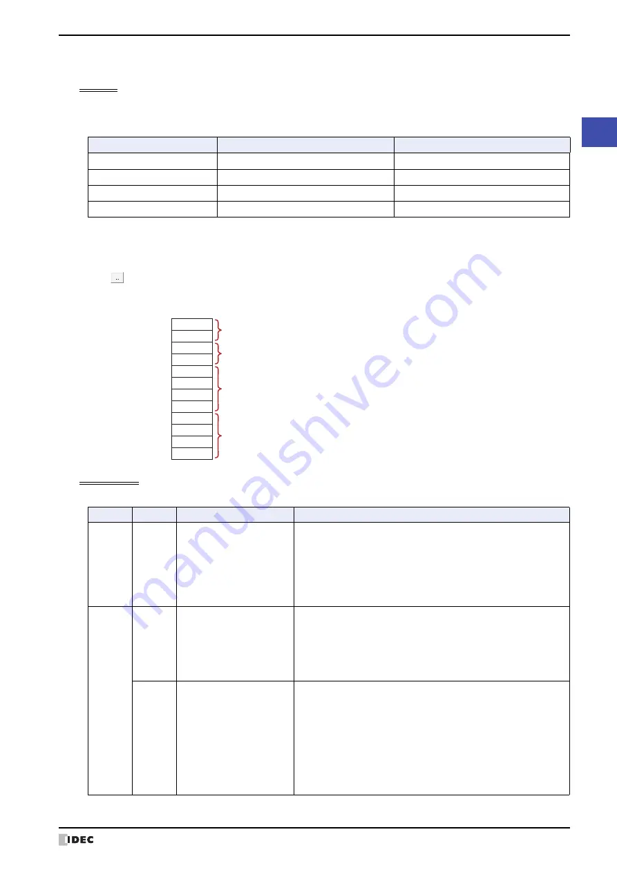
Example: When
Device
is configured as LDR100
System Area 1
This area configures the Touch display, beep, and clearing bits.
System Area
Number of word addresses
User Access
System Area 1
2
Read and write
System Area 2
2
Write
System Area 3
4
Read
System Area 4
4
Write
LDR100
LDR101
LDR102
LDR103
LDR104
LDR105
LDR106
LDR107
LDR108
LDR109
LDR110
LDR111
System Area 1
(Starting address)
+1
+2
+3
+4
+5
+6
+7
+8
+9
+10
+11
System Area 2
System Area 3
System Area 4
Address
Bit
Function
Description
+0
0 to 15
Display screen number
This bit stores the number of the screen being displayed. Write a
value to this bit to change the screen to that number. Immediately
after the power is turned on, the value configured by
Default
Screen
in the Project Settings dialog box is stored here.
If the screen number does not exist in the project data, an error
message (No screen data) is displayed. However, when 0 is written
to this bit, the screen is not switched and no error message is
displayed.
+1
0
Backlight
This bit stores the illumination state of the backlight. Write a value to
this bit to change the state.
0:
Off
Turns the backlight off.
1:
On
Turns the backlight on.
1
Blink backlight (1 sec. cycle)
This bit stores the screen blink state (1 sec. cycle). Write a value to
this bit to change the state. This bit is 0 immediately after the power
is turned on.
0:
Do not blink
Stop blinking the screen and turn it on.
1:
Blink
Blinks the screen in one second intervals.
When Blink backlight (1 sec. cycle) (1, bit 1) and Blink
backlight (0.5 sec. cycle) (1, bit 2) are both 1, the
screen blinks at one second intervals.
Summary of Contents for SmartAXIS Touch FT1A Series
Page 1: ...FT1A Series FT9Y B1390 4 SmartAXIS Touch User s Manual ...
Page 22: ...Contents Preface 21 SmartAXIS Touch User s Manual ...
Page 240: ...6 Using Library Screens 4 36 SmartAXIS Touch User s Manual ...
Page 416: ...2 Multi State Lamps 8 26 SmartAXIS Touch User s Manual ...
Page 558: ...9 Calendar 9 142 SmartAXIS Touch User s Manual ...
Page 668: ...6 Timer 11 52 SmartAXIS Touch User s Manual ...
Page 754: ...4 Using Data and Detected Alarms 13 34 SmartAXIS Touch User s Manual ...
Page 792: ...4 Using the Data 14 38 SmartAXIS Touch User s Manual ...
Page 810: ...4 Using the Data 15 18 SmartAXIS Touch User s Manual ...
Page 870: ...3 Text Manager 19 16 SmartAXIS Touch User s Manual ...
Page 924: ...6 Important Notes 20 54 SmartAXIS Touch User s Manual ...
Page 1036: ...5 User Communication 22 74 SmartAXIS Touch User s Manual ...
Page 1092: ...2 Monitoring on the Touch 24 26 SmartAXIS Touch User s Manual ...
Page 1142: ...2 Word Devices 27 18 SmartAXIS Touch User s Manual ...
Page 1186: ...2 Analog Cartridge 29 34 SmartAXIS Touch User s Manual ...
Page 1194: ...3 Handling Problems 30 8 SmartAXIS Touch User s Manual ...


