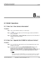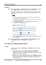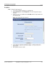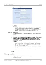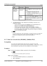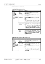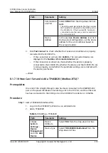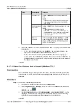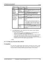
Path
Parameter
Setting
for adding
devices are
displayed.
Communicati
ons Port
Select COM2 from the drop-down list box.
NOTE
The setting example indicates that the
UPS2000G-A is connected to the COM2 port on
the ECC800-Pro. If the UPS2000G-A is
connected to another port, enter the number of
the connected port.
Device
Address
In this example, Device Address is set to 1.
During actual configuration, set the device
address for the UPS2000G-A based on the
actual situation.
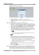
3. Click Test Connect to check whether the UPS2000G-A connects to the
ECC800-Pro properly.
–
If the connection succeeds, click Confirm. The connected devices are
displayed in the Number of connected devices list.
–
If the connection fails, check whether the UPS2000G is properly
connected to the ECC800-Pro, whether the UPS2000G and ECC800-Pro
are running properly, and whether the parameter settings are consistent
with the UPS2000G parameters.
NO TE
The section describes how to add a UPS2000G-A in a single UPS scenario. In a parallel UPS
scenario, if the common communications address of the Modbus card is added to the
ECC800-Pro, all UPS2000G-As can be connected to the ECC800-Pro.
----End
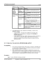
8.1.7.3 How Can I Set and Add a UPS2000G_L (Modbus-RTU)?
Prerequisites
One end of the straight-through cable has been connected to the CAN
communications port on the rear panel of the UPS2000G_L, and the other end has
been connected to the COM port on the ECC800-Pro or ETH converter.
Procedure
Step 1 Set the communications address parameters for the UPS2000G_L.
NO TE
For details, see the
UPS2000-G-6KRTLL User Manual
.
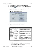
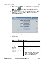
Step 2 Add a UPS2000G_L.
1. Log in to the ECC800-Pro WebUI as an administrator.
2. Add a UPS2000G_L.
ECC800 Data Center Controller
User Manual (for ECC800-Pro)
8 FAQ
Issue 02 (2020-09-07)
Copyright © Huawei Technologies Co., Ltd.
264

