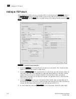
DCFM Professional User Manual
261
53-1001773-01
Adding an FCIP circuit
12
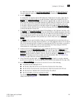
The default is created from the IP address and Subnet Mask. If you want to create a route
through a gateway router, click Create Non-Default Route, and select a Gateway address.
5. Enter the MTU Size.
For SAN traffic, the largest possible MTU (Maximum Transmission Unit) size is generally the
most efficient. If you have an active connection between switch one and switch two, click
Suggest under Switch One Settings. To determine a suggested size, packets are sent across
the FCIP tunnel, starting at the largest possible size packet that can be sent over IP. If a valid
connection response is not received, a smaller packet is sent. This continues until a valid
connection response is received, and that size becomes the suggested MTU. MTU settings
must match at both ends of the tunnel, and the setting specified under Switch One Settings is
automatically applied to switch two.
6. If a VLAN ID is used to route frames between the switches over the physical connection, enter
the VLAN ID under Switch One Settings. The same VLAN ID is automatically assigned to switch
two. The VLAN ID is an integer value between 1 and 4094 which sets the VLAN tag value in the
header assigning the traffic to that specific VLAN. Layer two class of service (L2CoS) values
may be assigned to establish traffic priorities over a VLAN. This is done as an Advanced
Setting.
7. The Metric option is used to identify a failover circuit. By assigning a non-zero metric (1), you
identify the circuit as a failover circuit. By default, a circuit is assigned a metric of 0. If a circuit
fails, FCIP trunking tries first to retransmit any pending send traffic over another circuit with a
metric of 0. If no circuits with a metric of 0 are available, then the pending send traffic is
retransmitted over any available circuit with a metric of 1.
8. Select values for bandwidth settings. An uncommitted bandwidth is not allowed on an FCIP
circuit. You must select Committed bandwidth. If you want to use ARL, set Minimum and
Maximum bandwidth values. Bandwidth grows towards the maximum and reduces towards the
minimum based on traffic conditions. If you do not want to use ARL, set Mimimum and
Maximum to the same value to set a single committed bandwidth. Refer to
“Adaptive Rate
Limiting”
on page 249 for more information about ARL.
9. If the physical connection exists, click Verify IP Connectivity to test the connection between
switch one and switch two. The IP connectivity of the connection is tested with the ping utility.
10. Select Advanced Settings and continue if you want to do any of the following:
•
Turn selective acknowledgement off.
•
Set the keep alive timeout to a value other than the default of 10 seconds.
•
Set the minimum retransmission time to a value other than the default of 100 ms.
•
Set the maximum retransmits to a value other than the default.
•
Use TCP/IP DSCP or L2CoS to prioritize FC traffic.
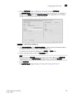
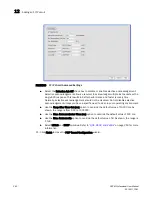
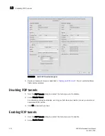
If you select Advanced Settings, the Transmission tab of the FCIP Circuit Advanced Settings
dialog box displays (
Figure 89
).
Summary of Contents for Brocade BladeSystem 4/12
Page 1: ...53 1001773 01 14 April 2010 DCFM Professional User Manual Supporting DCFM 10 4 X ...
Page 3: ...DCFM Professional User Manual iii 53 1001773 01 ...
Page 4: ...iv DCFM Professional User Manual 53 1001773 01 ...
Page 88: ...56 DCFM Professional User Manual 53 1001773 01 Seed switch 2 ...
Page 146: ...114 DCFM Professional User Manual 53 1001773 01 Customizing the main window 4 ...
Page 152: ...120 DCFM Professional User Manual 53 1001773 01 Launching HCM Agent 5 ...
Page 246: ...214 DCFM Professional User Manual 53 1001773 01 Syslog forwarding 8 ...
Page 262: ...230 DCFM Professional User Manual 53 1001773 01 Generating zoning reports 10 ...
Page 662: ...630 DCFM Professional User Manual 53 1001773 01 ...

