DCFM Professional User Manual
317
53-1001773-01
LLDP-DCBX configuration
13
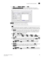
4. Select the Global Configuration LLDP profile in the LLDP Profiles table.
5. Click the left arrow button to edit.
6. Select the FCoE Application and FCoE Logical Link check boxes in the Advertise table to
advertise them on the network.
7. Click OK.
The CEE Confirmation and Status dialog box displays.
8. Click Start on the CEE Confirmation and Status dialog box to save the changes to the switch.
9. Click Close on the CEE Configuration dialog box.
Adding an LLDP profile
When LLDP is disabled on the switch, a yellow banner displays on the LLDP-DCBX dialog box,
indicating that LLDP-DCBX is not only disabled on the switch, it is also disabled for all ports and
LAGs on the switch.
1. Select Configure > Switch > CEE from the menu bar.
The CEE Configuration dialog box displays, showing the status of all CEE-related hardware and
functions.
2. Select a switch, and click Edit.
3. Click the LLDP-DCBX tab on the Edit Switch dialog box.
The LLDP-DCBX dialog box displays.
4. Click the Enable LLDP-DCBX checkbox.
5. Configure the LLDP Profile parameters:
•
Name - Type a name for the LLDP profile.
If the name of the LLDP profile already exists on the switch, an overwrite warning
displays.
You can change the <Global Configuration> name; when you click the right arrow
button, a new LLDP is created.
•
Description - Type a meaningful description of the LLDP profile.
•
Mode - Select a mode from the list: Tx (transmitted) or Rx (received).
•
Hello - Enter a hello interval time for the bridge. The value range is 4-180 and the default
value is 30.
•
Multiplier - Enter a multiplier. The value range is 1-10 and the default is 4.
•
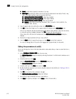
Advertise - Check the profile parameters that you want to display as part of the LLDP
profile:
•
Port description - The user-configured port description.
•
System name - The user-configured name of the local system.
•
System capabilities - The system capabilities running on the system.
•
System description - The system description containing information about the
software running on the system.
•
Management IP address - The IP management address of the local system.
•
Dot 1..Dot 3 -
Summary of Contents for Brocade BladeSystem 4/12
Page 1: ...53 1001773 01 14 April 2010 DCFM Professional User Manual Supporting DCFM 10 4 X ...
Page 3: ...DCFM Professional User Manual iii 53 1001773 01 ...
Page 4: ...iv DCFM Professional User Manual 53 1001773 01 ...
Page 88: ...56 DCFM Professional User Manual 53 1001773 01 Seed switch 2 ...
Page 146: ...114 DCFM Professional User Manual 53 1001773 01 Customizing the main window 4 ...
Page 152: ...120 DCFM Professional User Manual 53 1001773 01 Launching HCM Agent 5 ...
Page 246: ...214 DCFM Professional User Manual 53 1001773 01 Syslog forwarding 8 ...
Page 262: ...230 DCFM Professional User Manual 53 1001773 01 Generating zoning reports 10 ...
Page 662: ...630 DCFM Professional User Manual 53 1001773 01 ...

