


ENGINEERING MANUAL OF AUTOMATIC CONTROL
CHILLER, BOILER, AND DISTRIBUTION SYSTEM CONTROL APPLICATIONS
307
Anytime chilled water flow is proven via a chilled water pump
current sensing relay, the chiller controls shall be enabled to
operate under factory controls, subject to a chiller software ON-
OFF-AUTO function (chilled water flow must still be proven
in the “ON” mode). Provide control and interlock wiring per
the chiller manufacturers recommendation.
Upon a call for chilled water, the chiller controls shall start the
condenser water pump and energize the cooling tower fan controls.
When condenser water flow is proven via a condenser water
pump current sensing relay, the chiller shall start, operate, and
load under chiller factory controls to maintain the chilled water
temperature setpoint, 46F at start-up.
Anytime all chilled water valves are less than 85 percent open,
the chilled water temperature setpoint shall be incremented at
a rate of 0.3F every 10 minutes up to a maximum of 52F.
Anytime any chilled water valve is full open, the chilled water
temperature setpoint shall be decremented at a rate of 0.3F
degrees every 10 minutes down to a minimum of 45F.
The maximum allowable percentage of chiller full load
electrical current shall be commandable from the BMCS, and
shall be 80 percent during all unoccupied periods of operation.
MULTIPLE CHILLER SYSTEM
CONTROL APPLICATIONS
Multiple chiller systems offer standby capacity and improved
economy at partial loads. Multiple chiller systems may be piped
for either parallel or series chilled water flow.
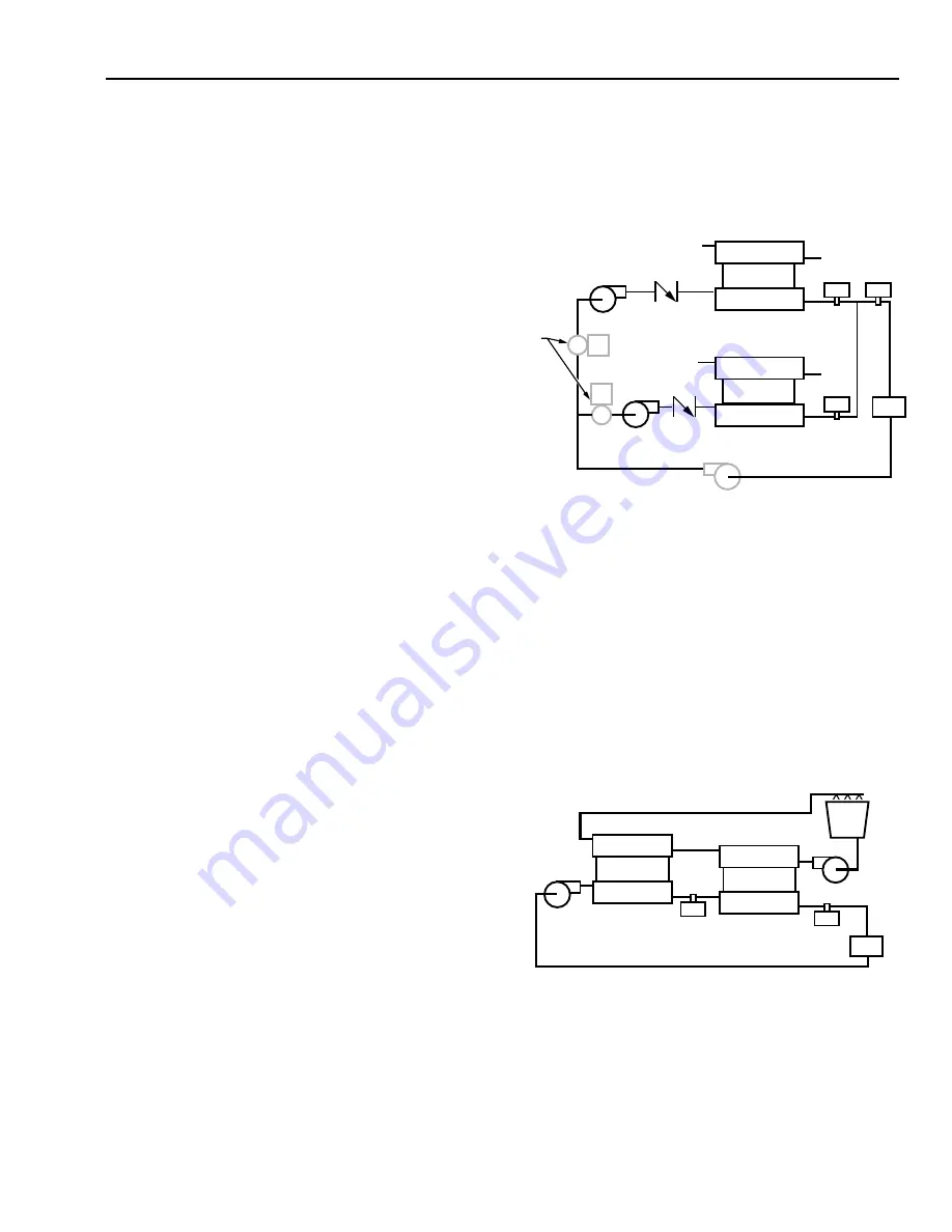
In the parallel piped arrangement (Fig. 11), return chilled
water is divided among the chillers then recombined after
chilling. Two methods of operation at light loads are depicted.
One uses a pump and a check valve for each chiller. The other
uses a common pump with an isolation valve for each chiller.
Multiple pumps with check valves allow one chiller and the
associated pump to be shut down during light load conditions
to save energy and require that the system be able to operate
with the reduced flow. The check valves prevent reverse flow
through the shut down chiller. Use of a common pump and
isolation valves require that the operating chiller be able to
withstand full system flow. The isolation valves allow the
operating chiller to supply only the chilled water temperature
required to meet system demands. Without the isolation valves,
half of the water flows through the chiller which is shut down
and is not cooled. When the uncooled water is mixed with the
cooled water, the temperature will be the average of the water
temperatures. As a result, the on-line chiller must supply water
cool enough so that the average will satisfy the primary sensor
and thus the system. To meet this requirement the on-line chiller
may need to supply water close to the freezing point.
The temperature sensor in the common chilled water supply
is the primary capacity control. The temperature low limit
control prevents the outlet temperature of each chiller from
going too low. A return water temperature sensor can be used
in conjunction with a supply water temperature sensor to turn
off one chiller in light load conditions.
Fig. 11. Parallel Piped Chillers.
In the series arrangement (Fig. 12) chilled water pressure
drop is higher if the chillers are not designed for higher flow.
At partial loads, compressor power consumption is lower than
for the parallel arrangement.
When the condensers of series units are water cooled, they
are piped in series counterflow to balance loading. When piped
series-counterflow, Chiller 1 receives warmer condenser and
chilled water while Chiller 2 receives colder entering condenser
and chilled water. This makes refrigerant head approximately
the same for each chiller. The controls may be set to shutdown
either chiller at partial loads.
CHILLER 2
CONDENSER
COMPRESSOR
EVAPORATOR
CONDENSER
COMPRESSOR
EVAPORATOR
CHILLER 1
LOAD
ISOLATION
VALVES
USED WITH
COMMON
PUMP
LOW
LIMIT
LOW
LIMIT
PRIMARY
SENSOR
C2691
COMMON
PUMP
CHILLER 2
CONDENSER
CONDENSER
COMPRESSOR
EVAPORATOR
COMPRESSOR
EVAPORATOR
CHILLER 1
LOAD
LOW
LIMIT
PRIMARY
SENSOR
C2692
Fig. 12. Series Piped Chillers.
Summary of Contents for AUTOMATIC CONTROL
Page 4: ...ENGINEERING MANUAL OF AUTOMATIC CONTROL iv ...
Page 6: ...ENGINEERING MANUAL OF AUTOMATIC CONTROL vi ...
Page 11: ...ENGINEERING MANUAL OF AUTOMATIC CONTROL CONTROL FUNDAMENTALS 1 CONTROL SYSTEMS FUNDMENTALS ...
Page 12: ......
Page 46: ...ENGINEERING MANUAL OF AUTOMATIC CONTROL CONTROL FUNDAMENTALS 36 ...
Page 66: ...PSYCHROMETRIC CHART FUNDAMENTALS 56 ENGINEERING MANUAL OF AUTOMATIC CONTROL ...
Page 128: ...ENGINEERING MANUAL OF AUTOMATION CONTROL ELECTRIC CONTROL FUNDAMENTALS 118 ...
Page 158: ...MICROPROCESSOR BASED DDC FUNDAMENTALS 148 ENGINEERING MANUAL OF AUTOMATIC CONTROL ...
Page 210: ...ENGINEERING MANUAL OF AUTOMATIC CONTROL BUILDING MANAGEMENT SYSTEM FUNDAMENTALS 200 ...
Page 440: ...ENGINEERING MANULA OF AUTOMATIC CONTROL INDIVIDUAL ROOM CONTROL APPLICATIONS 430 ...
Page 516: ...ENGINEERING MANUAL OF AUTOMATIC CONTROL GENERAL ENGINEERING DATA 506 Notes ...
Page 517: ...ENGINEERING MANUAL OF AUTOMATIC CONTROL GENERAL ENGINEERING DATA 507 Notes ...
Page 518: ...ENGINEERING MANUAL OF AUTOMATIC CONTROL GENERAL ENGINEERING DATA 508 ...


